background image

41

Northstar 

Explorer VHF Series: 721US, 721EU

 Operation and Installation Manual

Appendix B - Troubleshooting

1. The transceiver will not power up.

A fuse may have blown OR there is no voltage getting to the transceiver.

a)   Check the power cable for cuts, breaks, or squashed sections.

b)   After checking the wiring, replace the 7 Amp fuse (a spare fuse is supplied).

c)   Check the battery voltage. This must be greater than 10.5 V.

2. The transceiver blows the fuse when the power is switched on.

The power wires may have been reversed. 

a)   Check that the red wire is connected to the positive battery terminal, and the black wire is connected 

to the negative battery terminal.

3. The speaker makes popping or whining noises when the engine is running.

Electrical noise may be interfering with the transceiver.

a)   Re-route the power cables away from the engine.

b)   Add a noise suppressor to the power cable.

c)   Use resistive spark plug wires and/or use an alternator whine fi lter.

4. No sound from the external speaker.

a)   Check that the external speaker cable is physically connected.

b)   Check the soldering of the external speaker cable.

5. Transmissions are always on low power, even when high (HI) power is  selected.

The antenna may be faulty.

a)   Test the transceiver with a diff erent antenna.

b)   Have the antenna checked out.

6. Battery symbol is displayed.

The power supply is too low.

a)   Check the battery voltage. This should be at least 10.5 V ± 0.5 V DC.

b)   Check the alternator on the vessel.

7. No position information is displayed.

The GPS cable may faulty or the GPS setting may be incorrect. 

a)   Check that the GPS cable is physically connected.

b)   Check the polarity of the GPS cable.

c)   Check the baud rate setting of the GPS if applicable. The baud rate setting should be 4800 for NMEA 

or 38400 for NAVBUS.  Parity should be set to NONE.

Summary of Contents for VHF Marine Explorer 721EU

Page 1: ...www northstarnav com Explorer 721US 721EU VHF Marine Radio Operation and Installation Manual ...

Page 2: ... safety messages that follow this symbol to avoid possible injury or death WARNING indicates a potentially hazardous situation which if not avoided could result in death or serious injury CAUTION indicates a potentially hazardous situation which if not avoided could result in minor or moderate injury CAUTION used without the safety alert symbol indicates a potentially hazardous situation which if ...

Page 3: ...st CONTRAST 16 2 6 GPS Data and Time GPS DATA 17 2 7 GPS Simulator GPS SIM 20 2 8 Reset to Factory Defaults RESET 20 Section3 TheRadioSetupMenu RADIOSETUP 21 3 1 The Radio Setup Menu Options RADIO SETUP 21 3 2 Select the Channel Bank UIC 21 3 3 Change Channel Names CH NAME 21 3 4 Ring and Beep Volume RING VOL and KEY BEEP 22 3 5 Internal Speaker Connections INT SPEAKER 22 3 6 Set the Priority Chan...

Page 4: ...CV ALL SHIPS 35 5 11 Receive an Individual Call RCV INDIV 35 5 12 Receive a Group Call RCV GROUP 36 5 13 Receive a Geographic Call RCV GEOGRAPH 36 5 14 Receive a Polled Position Call RCV POSITION 36 Section6 DistressCalls 37 6 1 Send a Distress Call 37 6 2 Receive a Distress Acknowledgement DISTRESS ACK 37 6 3 Receive a Distress Call RCV DISTRESS 38 6 4 Relay a Distress Call RCV DISTRESS RELAY 38 ...

Page 5: ...ssions Notice This equipment complies with FCC radiation exposure limits set forth for an uncontrolled environment Thisdevice santennamustbeinstalledinaccordancewithprovidedinstructions anditmustbeoperated with minimum 96 cm spacing between the antennas and all person s body excluding extremities of hands wrist and feet during operation Further this transmitter must not be co located or operated i...

Page 6: ...or CH16 9 key for quick access to the priority international distress channel Special 3CH key to select your three favorite channels PSCAN similar to dual watch facility DSC Digital Select Calling capability that meets USCG SC101 for USA Class D Standards for EU Canada Commercial and Recreational Class S for Canada Distress call key to automatically transmit the MMSID and position until an acknowl...

Page 7: ...hrough numbers or hold down to scroll rapidly to the desired number Press CH to step through the alphabet or hold down to scroll rapidly to the desired character If you make an error press CH until is displayed then press ENT or push the rotary knob to backup and correct the entry If your radio has an alphanumeric microphone use the keypad to enter the cahnngel numbers and names Each key has the f...

Page 8: ...are selected Otherwise blank ATIS Enabled for use in European inland waterways Otherwise blank 721EU only DSC DSC capability is available ACK A message acknowledging your DSC call is being displayed Happy Fish symbol with one to four indicator bars to show the probability of good fishing at your current location based upon barometric pressure and air tempera ture Four bars show that good fishing is ...

Page 9: ...channel There is an incoming DSC DISTRESS call so the receiver is busy The latitude and longitude of the vessel and UTC time are shown 3 bars by the Happy Fish indicates rising barometic trends and reasonable fishing conditions The weather indicates showery conditions A typical operational display on Optional Handset LCD 1 6HowtheMicrophoneandOptionalHandsetWorkTogether If you have the optional ha...

Page 10: ...ea conditions In areas of high noise eg close to large cities reception may improve if sensitivity is reduced Either turn SQL slowly clockwise or use the LOCAL setting See section 2 4 DISTRESS Send DSC Distress Call See Section 6 16 9 Priority Channel 721US only Press to cancel all other modes and to tune into the priority channel Press again to return to your original channel The default is Chann...

Page 11: ...ess the radio set up menu see Section 3 and the DSC set up menu see Section 4 Press to enter the DSC call menu and to make DSC calls see Section 5 WX Weather Channel 721US only In USA and Canadian waters press to hear the most recently selected weather station The WX symbol is displayed on the LCD Press CH or CH to change to a different weather channel Press WX again to return to the most recent ch...

Page 12: ... available channels one at a time or hold down to scroll rapidly through all the available channels The current channel is shown on the LCD in BIG digits with an A or B designator suffix if ap plicable in small letters below the channel number See Appendix C for a listing of channel frequencies Press CH or CH to scroll the cursor up and down menu options on the LCD when navigating menus When editing...

Page 13: ...urn the GPS Simulator on off See Section 2 7 Reset factory settings See Section 2 8 Section 2 The Radio Menu MENU Hold down CALL MENU to show the radio menu options Sections 1 3 and 1 4 explain how to navigate around the menu and enter save and change data 2 1TheRadioMenuOptions MENU Show weather SNR or Happy Fish information on the handset See Section 2 2 UIC 721US only CH NAME RING VOLUME KEY BEE...

Page 14: ...splay 3 items of interest temperature Signal To Noise ratio SNR or HAPPY FISH quality a digital readout of the current air temperature F or C the current Signal to Noise Ratio SNR the Happy Fish symbol with indicator bars 1 Hold down CALL MENU to display the radio menu 2 The cursor is at INFO DATA Press ENT then select INFO ON to display the information on the handset LCD instead of the time and G...

Page 15: ...d at the top of your buddy list NOTE When the BUDDY LIST is full 20 entries you can t make a new entry until you have deleted an existing entry 2 3 2EditanEntry 1 Select BUDDY LIST Press ENT or push the rotary knob to display the list of entries 2 Scroll down if required to the incorrect entry and press ENT 3 Select EDIT The cursor is at the first character of the name 4 Edit the buddy name or to ...

Page 16: ...IST 2 Press ENT or push the rotary knob to activate the DIST setting This disables local sensitivity and the menu is displayed again 2 4 2SetLocalSensitivity 1 Select LOCAL DIST then scroll to LOCAL 2 Press ENT or push the rotary knob to activate the LOCAL setting This disables distance sensitivity and the menu is displayed again LOCAL is displayed on the LCD in reverse video as a reminder that lo...

Page 17: ...cted or absent you can specify the vessel position and the local time manually using the GPS DATA option This information is important because it will be used if you transmit a DSC distress call 2 6 1ManuallyEnterPositionandUTCTime MANUAL NOTE This function is available only when an operational GPS receiver is NOT connected 1 Select GPS DATA then MANUAL 2 Enter the latitude then the longitude then...

Page 18: ...ome places Map outline Mountain High Maps Compiled by HM Nautical Almanac Office Z A B C C D D E 0 1 2 3 3 30 4 4 30 5 E F F G H I I 5 30 6 6 30 7 8 9 9 30 K K L L M M M 10 10 30 11 11 30 12 13 14 N O P P Q R S 1 2 3 3 30 4 5 6 T U U V V W X Y 7 8 8 30 9 9 30 10 11 12 h h h h h m m m m m No Standard Time legally adopted Standard Time Universal Time value from table V X K L P Q Q R V U T S R Q P T ...

Page 19: ...LLdisplay If you ve entered the vessel position manually as described in the previous section the vessel position is shown ALWAYS with the suffix M However if the time is being updated through a GPS navigation receiver you can switch the vessel position display ON or OFF as follows 1 Select GPS DATA then SETTING 2 Select LL DISPLAY 3 Select ON or OFF as desired In this example OFF has been selected ...

Page 20: ...hen select ON or OFF as desired Whenever the GPS Simulator is turned ON simulated Speed Over Ground SOG Course Over Ground COG and LL position appear on the screen This data is updated automatically during the simulation IMPORTANT It s not possible to send a DSC transmission when you re in GPS Simulator mode 2 8ResettoFactoryDefaults RESET Use RESET to return every setting to the factory defaults ...

Page 21: ...nning mode ON or OFF 721US only See Section 3 7 Select NMEA or NAVBUS protocol for communications between the radio and any other instruments See Section 3 8 Select the barometric units calibrate the sensor turn the display ON or OFF See Section 3 9 Select the temperature units calibrate the sensor See Section 3 10 Select the HAPPY FISH alarm to be ON or OFF See Section 3 11 3 2 SelecttheChannelBa...

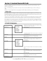
Page 22: ...sh the rotary knob 4 Press ENT or push the rotary knob repeatedly if necessary to display the YES NO confirmation 5 Press ENT or push the rotary knob to confirm the new channel name tag or the deletion then press ESC to return to the menu 3 4RingandBeepVolume RINGVOLUME and KEYBEEP Set the volume level of the incoming signal beeps RING VOLUME and or the error and warning beeps KEY BEEP as follows 1 ...

Page 23: ...alert is broadcast the alarm will sound Press any key to hear the weather alert voice message 3 8NMEAorNAVBUSprotocol COMPORT You can add the radio to a group of instruments using NMEA or NAVBUS protocol NAVBUS is automatically activated when present so that data such as barometric pressure and history temperature DSC polling positions and distress data are available to any other Northstar instrum...

Page 24: ...ards weather prediction and fishing conditions particularly when you re close to large land masses See the information on the Happy Fish icon in Section 1 5 The radio can show a weather icon to indicate five different conditions SUNNY PARTLY CLOUDY CLOUDY RAINY SNOW The local air pressure trends combined with the local temperature determines which weather icon is displayed NOTE In open ocean condi...

Page 25: ...ther station 3 10TemperatureDisplay TEMPERATURE A temperature sensor in the microphone measures air temperature changes 3 10 1SettheTemperatureUnits UNITS 1 Select RADIO SETUP then TEMPERATURE 2 The cursor is at UNITS Press ENT or press the rotary knob 3 The cursor is at ºC Press ENT or press the rotary knob to display the temperature in ºC Celsius or select ºF to show the temperature in Fahrenhei...

Page 26: ... of frequently called people stored in alphanumeric order A group MMSID always starts with 0 4 3 1CreateaGroup GROUPSETUP 1 Select DSC SETUP then GROUP SETUP 2 If this is the FIRST TIME that you re entering a group name a line of nine zeros appears Otherwise any existing group names are displayed Press ENT or push the rotary knob to display the input screen 3 Enter the group name along the dashed ...

Page 27: ...4 When you are finished press ENT or push the rotary knob repeatedly if necessary to display the next screen 5 Press ENT or push the rotary knob to store the changes and return to the GROUP SETUP screen 4 3 3DeleteaGroup 1 Select DSC SETUP then GROUP SETUP 2 Select the group that you want to delete 3 Select DELETE and press ENT or press the rotary knob The radio asks for confirmation 4 Press ENT or ...

Page 28: ...s ENT or push the rotary knob to confirm each correct entry and to move to the next digit If you make an error press CH until appears then press ENT or push the rotary knob to backup and correct the entry If you re editing an existing ATIS MMSID this will be displayed Make the required changes 3 Press ENT or push the rotary knob to store your ATIS MMSID 4 Enter your ATIS MMSID again as a password c...

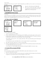
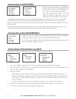
Page 29: ...N and DSC ON simultaneously When you enable one the other will turn OFF If DSC and ATIS are both OFF you must turn DSC ON for normal DSC operation The annunciator on the LCD shows you the current mode if the DSC annunciator is shown DSC is operational if the ATIS annunciator is shown ATIS is operational 4 7ResponseTypetoLLPollingCalls LLREPLY You can set up the radio to respond to an LL polling re...

Page 30: ... watches on distress frequencies and will be used to broadcast routine and urgent maritime safety information DSC enables you to send and receive calls from any vessel or coast station that is equipped with DSC functionality and within geographic range Calls can be categorised as distress urgency safety or routine and DSC selects a working channel automatically 5 2TheDSCCALLMenuOptions INDIVIDUAL ...

Page 31: ...oast Station the radio will recognize this and select the correct channel 5 The radio summarizes the call details and asks for confirmation to send the call SEND Press ENT or push the rotary knob to send the call The TX annunciator is displayed on the screen while the DSC call is being sent 6 If the call is acknowledged ACK press PTT to talk If there s no reply to a routine call try again see Secti...

Page 32: ... 3 5 6CallAllShips ALLSHIPS 1 Press CALL MENU to enter the DSC CALL menu then select ALL SHIPS 2 The priority is set automatically to URGENCY but you can change the priority level of the DSC call to routine safety urgency or distress Choose URGENCY only when there s a serious situation or problem that could lead to a distress situation SAFETY to send safety information to all other vessels in rang...

Page 33: ...e rotary knob to send the call Continue as explained in Section 5 3 5 8CallusingtheDistressLog DISTLOG The Distress Log contains the data for the 10 most recent relayed distress calls so that you can call any of them quickly Always try to make voice contact on CH16 first as follows 1 Press CALL MENU to enter the DSC CALL menu then select DIST LOG 2 The most recently received distress call is the fir...

Page 34: ...NU to enter the DSC CALL menu then select TRACK BUDDY 2 Select SET BUDDY then select the buddy you want to track You can set a maximum of 3 buddies to track 3 Select ON to track that buddy or OFF to not track that buddy and press ENT or push the rotary knob to confirm Repeat for the other two buddies if necessary To delete a buddy from the tracklist just scroll to the buddy s name and press ENT or ...

Page 35: ...ts CH16 TheprioritylevelandtheuserMMSIDaredisplayedontheLCD Iftheradiorecognises the user MMSID as one of your buddies the buddy s name is displayed in place of the user MMSID No acknowledgement is required Press PTT to initiate voice contact on CH16 and then switch to a working channel The call data is stored in the Call Log see Section 5 7 5 11ReceiveanIndividualCall RCV INDIV When you receive n...

Page 36: ... the Call Log see Section 5 7 5 13ReceiveaGeographicCall RCV GEOGRAPH A geographic call is sent to all vessels within a specific geographic boundary area When you receive notification of a GEOGRAPH call press any key to cancel the alert The radio automatically selects the channel designated in the incoming call The time and the user MMSID or name are displayed on the screen If the radio recognises t...

Page 37: ...ing voice contacts from search and rescue authorities or other vessels within range Press ESC if you need to cancel the distress call This is the only key that operates in distress mode 6 2ReceiveaDistressAcknowledgement DISTRESSACK The Coast Guard is the only agency allowed to send a Distress Acknowledgement DISTRESS ACK When a distress acknowledgement is sent from the Coast Guard your radio auto...

Page 38: ...nds when a distress relay DISTRESS RELAY is received from an individual or from an All Ships transmission Press any key to cancel the alert Try to make voice contact with the calling vessel Maintain a listening watch on CH16 and standby to lend assistance 6 3RelayaDistressCallfromtheDistressLog RELAY You can relay a Distress Call in your Distress Log to an Individual or to All Ships 1 Press CALL M...

Page 39: ...N 4 x 12 character Contrast control Yes Backlight control Yes Antenna connector SO 239 50 ohm Temperature Range 15ºC to 50ºC Waterproof JIS 7 Dimensions 161 W x 75 H x 147 D mm without bracket Weight 3 0 lbs 1 36 kg without microphone Frequency stability 10ppm Frequency control PLL GPS NMEA input Yes Comm port 4800 baud NMEA 38400 baud NAVBUS DSC Yes Rotary channel selector Yes FEATURES Flush moun...

Page 40: ... of antenna Max Freq deviation 5 kHz Spurious harmonics better than 2 5 W Modulation distortion Less than 4 1 kHz for a 3 kHz deviation RECEIVER Frequency 156 025 163 275 MHz 12 dB SINAD sensitivity 0 25 uV distant 2 5 uV local Adjacent CH selectivity more than 70 db Spurious response more than 70 db Intermodulation rejection ratio more than 68 db Residual Noise level more than 40 db unsquelched A...

Page 41: ...ute the power cables away from the engine b Add a noise suppressor to the power cable c Use resistive spark plug wires and or use an alternator whine filter 4 No sound from the external speaker a Check that the external speaker cable is physically connected b Check the soldering of the external speaker cable 5 Transmissions are always on low power even when high HI power is selected The antenna may...

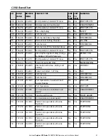
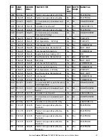
Page 42: ... 800 x x x 64 m o 156 225 160 825 x x x 05 m o 156 250 160 850 x x x 65 m o 156 275 160 875 x x x 06 f 156 300 x 66 156 325 160 925 x x 07 156 350 160 950 x x 67 h 156 375 156 375 x x 08 156 400 x 68 156 425 156 425 x 09 i 156 450 156 450 x x 69 156 475 156 475 x x 10 h 156 500 156 500 x x 70 j 156 525 156 525 Digital selective calling for distress safety and calling 11 156 550 156 550 x 71 156 57...

Page 43: ...162 025 SPECIAL NOTES ON INTERNATIONAL CHANNEL USEAGE Notes referring to the Table General notes The International mode is not legal for use in US or Canada Waters a Administrationsmaydesignatefrequenciesintheinter ship portoperationsandshipmovementservices for use by light aircraft and helicopters to communicate with ships or participating coast stations in pre dominantly maritime support operati...

Page 44: ... required by the individual administrations concerned for communication between ship stations aircraft stations and participating land stations engaged in coordinated search and rescue and anti pollution operations in local areas under the conditions specified in Nos 51 69 51 73 51 74 51 75 51 76 51 77 and 51 78 i The preferred first three frequencies for the purpose indicated in Note a are 156 450 ...

Page 45: ...Yes No BRIDGE COM 14 156 700 156 700 Port Operations Selected VTS Areas Yes Yes PORT OPS VTS 15 2 RX Only 156 750 Environmental RX Only ENVIROMENTAL 16 156 800 156 800 International Distress Safety and Calling Yes Yes DISTRESS 17 1 156 850 156 850 State Controlled 1W Only Yes Yes SAR 18A 156 900 156 900 Commercial Yes Yes COMMERCIAL 19A 156 950 156 950 Commercial Yes Yes COMMERCIAL 20 157 000 161 ...

Page 46: ...erations Recreational Yes No SHIP SHIP 73 156 675 156 675 Port Operations Yes Yes PORT OPS 74 156 725 156 725 Port Operations Yes Yes PORT OPS 77 1 156 875 156 875 Port Operations 1W Only Yes Yes PORT OPS 78A 156 925 156 925 Boat Operations Recreational Yes No SHIP SHIP 79A 156 975 156 975 Commercial Yes Yes COMMERCIAL 80A 157 025 157 025 Commercial Yes Yes COMMERCIAL 81A4 157 075 157 075 U S Gove...

Page 47: ...ES ON USA CHANNEL USAGE 1 LOW POWER 1 W only 2 Receive Only 3 LOW POWER 1W initially Override to HIGH POWER by holding down H L key before transmitting Used normally in bridge to bridge communications 4 Lightly Shaded Simplex channels 03A 21A 23A 61A 64A 81A 82A and 83A cannot be lawfully used in U S waters unless special authorization is obtained from the U S Coast Guard Not for use by the genera...

Page 48: ...W with power up Yes No BRIDGE COM 14 156 700 156 700 Port Operations VTS in Selected Areas Yes Yes PORT OPS VTS 15 1 156 750 156 750 Commercial 1W Only Yes Yes COMMERCIAL 16 156 800 156 800 International Distress Safety and Calling Yes Yes DISTRESS 17 1 156 850 156 850 State Controlled 1W Only Yes Yes SAR 18A 156 900 156 900 Commercial Yes Yes COMMERCIAL 19A 156 950 156 950 Canadian Coast Guard Ye...

Page 49: ...onal Yes Yes PLEASURE 72 156 625 156 625 Intership Yes No SHIP SHIP 73 156 675 156 675 Commercial Fishing Only Yes Yes COMMERCIAL 74 156 725 156 725 Commercial Fishing Only Yes Yes COMMERCIAL 77 1 156 875 156 875 Port Operations 1W Only Yes Yes PORT OPS 78A 156 925 156 925 Boat Operations Recreational Yes No SHIP SHIP 79A 156 975 156 975 Commercial Yes Yes COMMERCIAL 80A 157 025 157 025 Commercial...

Page 50: ...W POWER 1 W only 2 Receive Only 3 LOW POWER 1W initially Override to HIGH POWER by holding down H L key before transmitting Used normally in bridge to bridge communications 4 Lightly Shaded Simplex channels 21A 23A 61A 64A 81A 82A and 83A cannot be lawfully used in Canada waters unless special authorization is obtained from the Canadian Coast Guard Not for use by the general public 5 The letter A ...

Page 51: ...56 175 160 775 x 4 a 156 2 160 8 x 64 a 156 225 160 825 x 5 a 156 25 160 85 x 65 a 156 275 160 875 x 6 a b 156 3 156 3 x 66 a 156 325 160 925 x 7 a 156 35 160 95 x 67 a c 156 375 156 375 x 8 a q 156 4 156 4 x 68 a 156 425 156 425 x 9 a b c 156 45 156 45 x 69 a 156 475 156 475 x 10 e 156 5 156 5 x 70 a 156 525 156 525 Digital selective calling for distress saftey and calling 11 156 55 156 55 x 71 1...

Page 52: ...0 157 025 161 625 x 21 a 157 05 161 65 x 81 a 157 075 161 675 x 22 157 1 161 7 x 82 l m 157 125 161 725 x 23 m 157 15 161 75 x 83 a m 157 175 161 775 x 24 m 157 2 161 8 x 84 m 157 225 161 825 x 25 m 157 25 161 85 x 85 a m 157 275 161 875 x 26 m 157 3 161 9 x 86 a m 157 325 161 925 x 27 m 157 35 161 95 x 87 a d 157 375 157 375 x 28 m 157 4 162 x 88 a p 157 425 157 425 x AIS 1 a n 161 975 161 975 AI...

Page 53: ...f In the countries mentioned under 1 1 2 this channel is used for service category ship to port authori ties g In the Netherlands this channel is used by its national coastguard for communications during oil pol lution operations on the North Sea and for safety messages for the North Sea Waddenzee IJsselmeer Ooster and Westerschelde h This channel may be used only for service category on board on ...

Page 54: ...sure who to contact consult your Northstar dealer The user MMSID is a unique nine digit number similar to a personal telephone number It is used on marine transceivers that are capable of using DSC Digital Select Calling Depending upon your location you may need a radio station license for the VHF 721 You may also need an individual operator s license Brunswick New Technologies Inc recommends that...

Page 55: ...least 3 1 m from the antenna allows easy connection to at least a 10 Amp fused 13 6 V DC electrical source and the antenna is at least 1 5 45 cms from the compass to avoid creating magnetic deviation of the compass during radio operation has a suitable space close by for installing the microphone bulkhead mount provides easy access to the controls on the front panel provides reasonable access to t...

Page 56: ...larity 23 Explorer 721 base unit and microphone not pictured 24 Explorer 721 protective cover not pictured 7 4GimbalInstallation 1 Hold the mounting gimbal at the chosen location and use a soft pencil to mark the screw hole positions onto the mounting surface 2 If you can t reach behind the mounting surface to attach the nuts use the self tapping screws instead of the flat screws shown in the pictu...

Page 57: ... the installation template onto the chosen location site 2 Cut out the area marked by the solid dark line The dashed line indicates the total area that will be covered by the radio fascia after installation 3 Remove the installation template and slide the radio into the cavity 4 Working from the rear of the bulkhead align the racheted outstand on each side of the radio with the central hole in eac...

Page 58: ...icrophone on its mount NOTE This mic clip has a special magnet glued in the rear of the clip to sense ON OFF HOOK Other mic hangers cannot be used 7 8ConnecttheRadioCables The connectors are on the rear of the base unit as follows 1 GPS connector Plug the GPS cable jack into the connector If you re not using this be sure to put the protective cap securely over the connector to protect it from mois...

Page 59: ...t are capable of using DSC Digital Select Calling If you don t have a user MMSID contact the appropriate authorities in your country If you re unsure who to contact consult your Northstar dealer 7 10EnterYourUserMMSID WARNING This is a once only operation 1 Select DSC SETUP then USER MMSID A dashed line appears Enter your user MMSID along the dashed line Press ENT or push the rotary knob to confirm...

Page 60: ...letedInstallation withOptionalHandset M84 M84 Battery VHF Antenna Wallplate on bulkhead Northstar GPS product Handset docking cable Antenna connection cable External speaker BLACK power cable Fuse on RED power cable Optional Handset External speaker connection cable Base unit with microphone ...

Page 61: ...cean Quay Belvidere Rd Southampton SO14 5QY England Ph 44 2380 339922 Fax 44 2380 330345 northstaruk northstarnav com AUSTRALIA PO Box 479 Gladesville NSW 2111 Australia Ph 61 2 9879 9000 Fax 61 2 9879 9001 northstaraus northstarnav com NEW ZEALAND PO Box 68 155 Newton Auckland New Zealand Ph 64 9 481 0500 Fax 64 9 481 0590 northstarnz northstarnav com www northstarnav com 0560 ...

Reviews: