background image

Page 12

tROUBlE-ShOOtING – CONt.

#585 repeatedly relearns the environment 

with each door position.

1.  Data polarity at the #585 is incorrect.

1.   Allow the door to open in the automatic 

mode. Unlock the #585 and launch a 

setup by pressing the Setup key, followed 

by the number 2. If the sensor does not 

begin flashing green, and instead goes 

back to a red indication, improper data 

exists.

2.  Check for proper polarity at terminal 6 

and 7. The negative wire from the lockout 

(white) should be connected to terminal 

6, and the red/white striped wire from 

the lockout should connect at terminal 7. 

•  HELPFUL HINT: If faulty data is suspected, 

simply power the door to the open 

position (by activation OR with the use 

of a hold open switch). While the door 

is open, unlock the #585, and press 

the setup key, followed by the number 

2. If the sensor goes back to a red LED 

(as opposed to flashing the green LED 

to indicate a setup), there is a strong 

probability that the data is incorrect. 

#585 not reacting to the remote control.

1.  Batteries in the remote control are dead.

2.  Distance between sensor and remote is 

too far.

1.  Replace batteries in the remote control.

2.   Move in closer to the sensor when 

programming.

3.   If remote control fails, manual 

programming procedures may have to be 

used (See Pg. 9). 

Norton Door Controls

3000 Hwy 74 East

Monroe, NC 28112

Tel: 877-974-2255

www.nortondoorcontrols.com

80-9359-0005-020-5/11

Summary of Contents for 585

Page 1: ...thout the use of the hand held remote Technical Specifications Installation Height Variable 9 0 max Recommended 6 6 to 8 0 Mounting Angles 5 10 factory default setting 5 Power Supply 12 to 24 V AC DC 10 Frequency 50 60 Hz Output Max Voltage at contacts 60V DC 125V AC Max Current at contacts 1 A Max switching power 30 W DC 60 VA AC Relay Hold Time 0 5 to 9 seconds Operating Temperature 22 F to 140 ...

Page 2: ...INSTALLATION PLACEMENT OF THE SENSOR Remember these guidelines when installing a 585 The 585 should be mounted at a height range of 6 6 to 8 Maximum mounting height is 9 The 585 should be mounted above the door on the swing side The 585 shall be mounted flush with the bottom of the frame This is absolutely necessary to allow the detection pattern to reach back through the threshold area when the 5...

Page 3: ... Picture 8 in the header for ease of screw installation Ensure that 585 is mounted securely at each end 3 If 585 is mounted directly to door header and cabling is to pass directly into header drill a hole next to the 585 s left side end cap to allow wire passage into header Picture 9 The wire passage hole should be in a location that aligns with the cut out in the end cap Picture 9 ELECTRICAL INST...

Page 4: ...e the farther from the door the pattern will be The 0º angle should only be used when the 585 is mounted to a soffit above the door that extends out from the face of the safety side of the door in this case the 0º setting would improve the location of the detection field across the threshold area of the doorway It is recommended that for most applications the unit be powered and walk tested at the...

Page 5: ...nd the sensor stayed red in detection it probably did not get the correct data signal from the respective lockout module As a preliminary check to the troubleshooting be sure to check that the voltage from the motor at the red and black wire of the lockout has at least 10 volts DC A voltage that is too low may not be recognized by the lockout 2 If the door goes to the open position and a setup is ...

Page 6: ... to adjust the pattern for door closed and then to adjust the pattern again when the door is open The following functions may be independently adjusted for each door position Sensitivity Pattern Width Pattern Depth 2 The following functions apply to both door closed and door open positions Automatic Learn Time Immunity Frequency Output Configuration Door Control Mode Hold Time Interface Type 3 The...

Page 7: ...Page 7 585REM Remote Control Programming GUIDE GENERAL functions ...

Page 8: ... adjustments Threshold The Threshold is always OFF when the door is closed Pattern Width or Depth When pattern width or depth is changed a setup of the new pattern size will automatically be triggered once a value key has been pressed ...

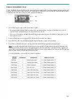
Page 9: ...reen LED will flash at a slower rate Press PB1 to re launch the set up 2 To change the detector s parameters press PB1 for more than 2 seconds then release 3 Press either PB1 or PB2 The LED will immediately flash red followed by a sequence of green flashes 4 The red flashes indicate the parameter and the green flashes indicate the setting of the particular parameter NOTE Pressing PB1 will toggle b...

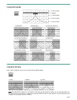
Page 10: ...d door position NOTE When the 585 is mounted at 7 each block on the pattern charts shown above equates to a size of approximately 14 x 14 Pattern sizes shown are only as an approximation Always walk test the pattern once complete to insure compliance with all applicable safety and performance standards ...

Page 11: ...using the 585 mounting block if NECESSARY 3 Ensure that no high intensity lighting is in the immediate area of the sensor Door will not open once set up has been completed 1 585 is in detection 2 Improper wiring 3 Improper relay output configuration 1 Ensure that there is no detection occurring at the 585 If the Red LED is on steady there is detection Make sure there have been no changes in the fi...

Page 12: ... If faulty data is suspected simply power the door to the open position by activation OR with the use of a hold open switch While the door is open unlock the 585 and press the setup key followed by the number 2 If the sensor goes back to a red LED as opposed to flashing the green LED to indicate a setup there is a strong probability that the data is incorrect 585 not reacting to the remote control...

Reviews: