8
2.3 Layout
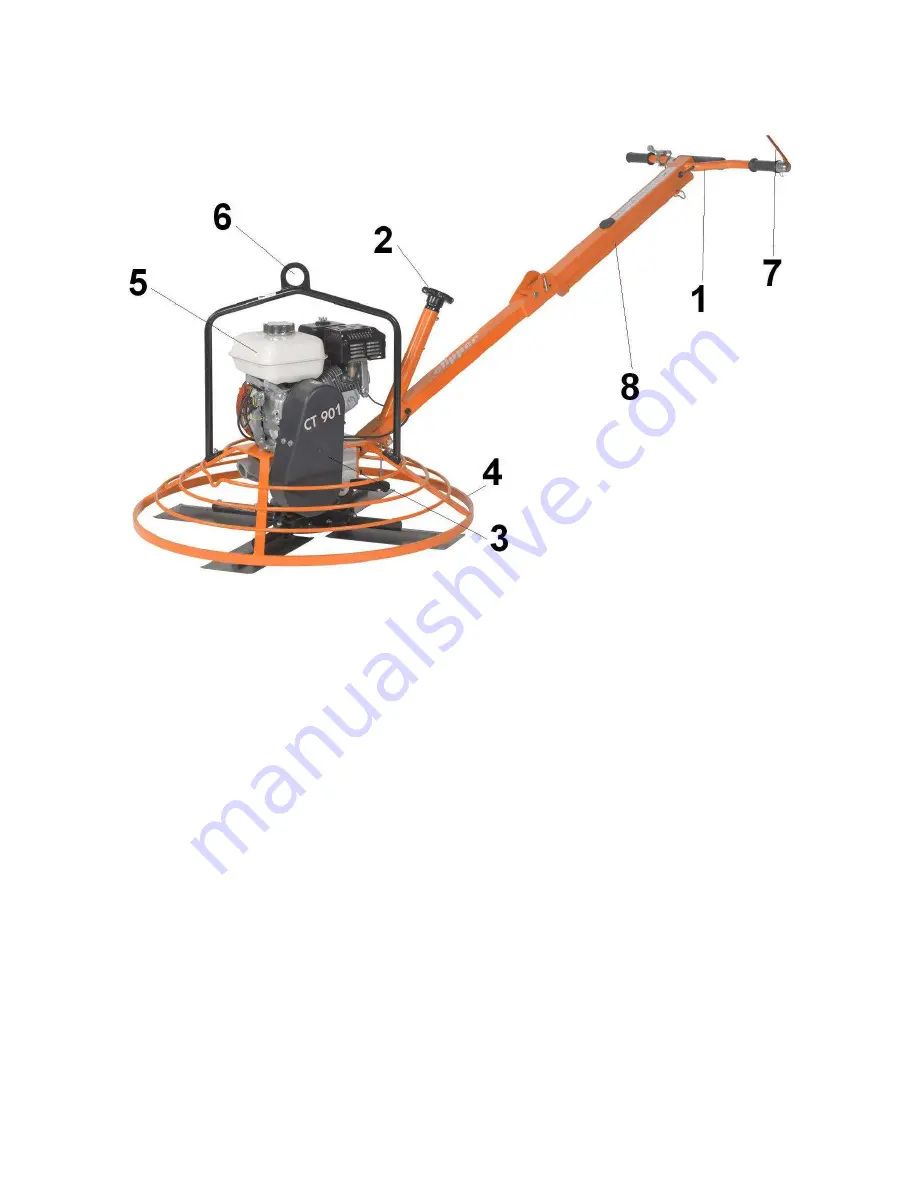
Handle (1)
Jig welded steel construction including 2 rubber grips. A dead-man handle (7) allows the operator to
work safely and to stop the machine at any moment. The angle of the machine arm can be adjusted
to operate the machine comfortably. A tube (8) is located under the handle; this will help you
transport the machine per hand.
Pitch of the blades (2)
The pitch of the blades is controlled over a knob on the handle.
Belt drive and belt cover (3)
A centrifugal clutch inside the motor pulley drives the gear shaft through V-Belts. It allows to
gradually engage the tool rotation. The drive assembly is enclosed in a metal guard.
Safety guard ring (4)
A safety guard ring protects the operator from the rotation of the tool while offering an optimum
view of the working progress. This ring can rotate, in order to ease the finishing of floor up to walls.
Electrical Motor (5)
Electrical motor with 2,2kW.
Lifting eye (6)
To lift the machine easily and safely, a lifting eye is located over the motor. This allows a balanced
lifting of the machine.


