background image

Operation Instruction 

17 


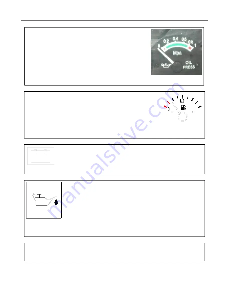
Figure 2.5 Oil Pressure Gauge 


Oil Pressure Gauge


The oil pressure gauge indicates the oil pressure in the engine           

in Mpa. 

Direction of the pointer: 

Increasing oil pressure is indicated as the pointer moves to the right.


Fuel Gauge


The fuel gauge indicates the level of diesel fuel in the fuel tank. 

Direction of the pointer: 

Rightmost position: Indicates that fuel tank is filled. Leftmost position:   

Indicates that there is not enough fuel in the tank and it should be filled immediately.    Figure 2-6 Fuel Gauge 


                              Charging Indicator (Red) 

                                  After the engine is started, the charge indicator goes out, which means the battery   

                                  is charged normally. Check and repair if the indicator does not go out.   


Figure 2-7 Charging Indictor Lamp 


Engine Oil Pressure Warning Lamp (Red) 

When the key is turned to the ignition position, the lamp is lit. After the engine has 

started, the lamp will go out. This means that the oil lube system pressure is normal. 

When the engine is at idle, the light may be illuminating. This is normal; the pressure 

in the lubrication system is low during the idling period. If the lamp is light when the 

engine is run at normal rpm, the tractor should be shut down and you should 

                                        troubleshoot the problem. 

Figure 2-8 Engine Oil Pressure Warning Lamp 


IMPORTANT NOTE

:

 The key should be switched to the ignition position before starting the engine. 

Check if the above three lights are illuminating. If they are not illuminating, the bulbs could be damaged or the 

circuit faulty. Overhaul immediately. 


Summary of Contents for 82XTC

Page 1: ...NorTrac 82XTC Tractor Owner s Manual Sold By Northern Tool Equipment Inc P O Box 1299 Burnsville MN 55337 Tel 1 800 222 5381 www northerntool com YFXT82OMAN...

Page 2: ...assis Serial Number Engine Model Engine Serial Number Date of Purchase Where Purchased Contact Information Owner Name Complete this form carefully at purchase All SN s in this form should be recorded...

Page 3: ...ion on the safest and most effective use of the tractor It will help you and others you might train to operate the tractor safely and correctly If you use the tractor with an implement or other attach...

Page 4: ...s manual is an integral part of the product and should be kept with the tractor Please keep it in a safe dry place If you encounter any sections that you do not understand while going over the manual...

Page 5: ...operation 27 2 10 How to use the front axle drive 27 2 11Tractor braking 28 2 12 Stopping the tractor and engine shutdown procedures 29 2 13 Tire assembly and disassembly 29 2 14 Counterweights 31 2 1...

Page 6: ...e 82 4 12 Hydraulic suspension system maintenance 85 4 13 Air filter use and maintenance 88 5 Storage 89 5 1 Tractor storage causes of damage 89 5 2 Tractor storage 89 5 3 Tractor storage maintenance...

Page 7: ...The driver should read and understand this operator s manual 4 Drive slowly at first in order to test your skill level Clothing During the operation the driver should avoid loose fitting clothing Bag...

Page 8: ...then turn the cap to the first position Once pressure has been reduced you can then remove the cap Fig 1 7 Removing the radiator cap Electric Parts Maintenance 1 Remove the ignition switch key 2 Never...

Page 9: ...er leave the driver s seat to start and operate the tractor Prior to the startup make sure that various shift levers are in the neutral position the throttle lever and the front drive control handle a...

Page 10: ...he tractor over the specified limits can cause damage to the tractor and can result in injury 17 When driving at night make sure that you have proper lighting to avoid any collisions 18 When working i...

Page 11: ...the tank to cool for 30 minutes 7 Pay attention to all safety precautions when replacing or installing new parts on your tractor IMPORTANT ISSUES 1 Always operate the tractor according to the specifie...

Page 12: ...lutch system 9 When detaching the tractor from any implements the upper lever of the suspension unit should be adjusted to the shortest travel and the limit lever adjusted to prevent the implements fr...

Page 13: ...fety warning identifier Never sit on the fender when the tractor is operating as this could result in falling from the vehicle and possible injury Location front side of the mudguard Fig 1 12 Safety w...

Page 14: ...secure position in the driver s seat Location in front of the instrument panel Read and understand all instruction for use including the meaning of all non lettered safety symbols Location in front o...

Page 15: ...fuel tank Fig 1 21 Refueling fire protection identifiers To prevent personal injury please install the safety shield on the PTO shaft when it is not in use Location on the pneumatic brake cylinder Fi...

Page 16: ...n error The operator either forgot something took a shortcut or a risk ignored a warning wasn t paying close attention or failed to follow safety rules In addition guards removed for maintenance often...

Page 17: ...signed to draw crops into the machine also create pinch points Fingers hands and feet can be caught directly in pinch points or they may be drawn into the pinch points by the inertia of the moving par...

Page 18: ...into the hitching position If possible arrange the hitch point so that the tractor can be backed into position without anyone between Always know what the other person is doing Failure to safely block...

Page 19: ...contain fluid under extreme pressure Before loosening tightening removing or otherwise working with any fittings or parts relieve this pressure Jet streams from even pinhole leaks can penetrate flesh...

Page 20: ...2 1 Common Symbols Symbols Definition Symbols Definition Symbols Definition Safety warning identifier Four wheel drive Horn High beam Low beam Quick Engine oil pressure Charging and discharging indic...

Page 21: ...gh lifting capacity and are easy to maintain 2 3 Tractor Operating Mechanisms and Instrumentation 2 3 1 Tractor Operating Mechanisms Figure 2 1 Tractor Control Mechanisms 1 Power take off cotrol handl...

Page 22: ...the tractor the driver should observe the various instruments and indicator lights If anything abnormal occurs you should stop the tractor and troubleshoot the problem Engine Tachometer After the the...

Page 23: ...Check and repair if the indicator does not go out Figure 2 7 Charging Indictor Lamp Engine Oil Pressure Warning Lamp Red When the key is turned to the ignition position the lamp is lit After the engi...

Page 24: ...hat the head light is on high beam Figure 2 10 Head Light High Beam Indicator Lamp Left Turn Indicator Green When the tractor is turning left and the left turn signal is on the left indicator light sh...

Page 25: ...high beam headlights if dimmer switch is set to 2 Position 1 Position Turns on taillights and low beam headlights 0 Position Turns off headlights and taillights Figure 2 16 Headlight Taillight Switch...

Page 26: ...osition Left turn signal on 0 Position Power supply off 2 Position Right turn signal on Figure 2 22 Steering Switch Rear Windshield Wiper Switch with optional cab 1 position Turns on the rear wiper 0...

Page 27: ...t could cause an accident 2 Check the radiator regularly and make sure that you have a clean water antifreeze mix to avoid overheating of the engine 2 4 1 Engine Starting Preparation 1 Before starting...

Page 28: ...high low shift lever the shuttle gear shift lever and the front drive control lever are in the neutral position and the 3 point lift control lever is in the lowering position This will prevent the tr...

Page 29: ...ted release the key immediately It will automatically return to the ON position NOTE Amp meter should drop to 30 Figure 2 26 Ignition Switch Starting the Engine in Low Temperatures below 40 F When sta...

Page 30: ...d be in the green zone 5 When running the engine the oil pressure and coolant temperature should be checked regularly During the normal operations of the engine the cooling temperature should be aroun...

Page 31: ...t cause damage to the hydraulic steering system due to an overload 2 When operating in the field prior to turning or backing up the parts and components of a towed implement need to be lifted clear of...

Page 32: ...sh it forward and it will be forward low gear FL Press the main clutch pedal to the floor and move the main gear shift lever A to the left from NEUTRAL then pull it backward to Gear 1 Push it forward...

Page 33: ...ed position 4 Step on the differential pedal to engage it 5 Release the clutch pedal smoothly for stable operation 6 After getting unstuck or stopping the skid the differential lock will automatically...

Page 34: ...y step on the brake pedal to stop the tractor In an emergency step on the clutch and brake pedal simultaneously Never step on the brake pedal without disengaging the clutch as this will cause sharp we...

Page 35: ...res are important parts of the tractor Attention should be paid to their use and maintenance in order to prolong tire service life All of the tires have specified load values An overload will deform t...

Page 36: ...be checked regularly Failure to do so can result in excessive tire wear When tire wear is nonuniform the left and right tires can be switched IMPORTANT ISSUES The inflation pressure for the front and...

Page 37: ...the rear wheel from the tractor first remove the counterweight from the tire to avoid an accident 2 14 2 Front Counterweights In order to adjust the front and rear axle loads of the tractor it is nec...

Page 38: ...d an accident 2 Making the seat too soft can make running the tractor on uneven surfaces particularly challenging and can cause a loss of sight lines 2 16 Hydraulic Suspension PTO and Electrical Syste...

Page 39: ...ore delivery of the tractor the descending speed regulating valve was adjusted The owner operator can readjust the valve according to the weight of farm implement and ground hardness To decrease the l...

Page 40: ...hould be used to lock the implements in place This will prevent an accidental move of the distributor control handle from making the farm implements drop suddenly and cause damage 2 16 4 Hydraulic Con...

Page 41: ...e hoses to the oil inlet and outlet of the double acting oil cylinders on the farm implement The multiway valve has four female connectors A1 B1 A2 and B2 A1 and B1 form the first group of the hydraul...

Page 42: ...ght lifting rod is shortened the tilling depth of the first plowshare will be shallower In general the left lifting rod C should not be adjusted The left lifting rod is adjusted only when the adjustme...

Page 43: ...or the adjustable 3 point arm and the limit rod should also be tightened to prevent wide swings of the implement during transport IMPORTANT ISSUES 1 When a fast change coupler is not used the seat hol...

Page 44: ...d turn the PTO disconnect control handle to the connected position Release the clutch pedal slowly First operate with the throttle at low speed to check whether the PTO is working properly When repeat...

Page 45: ...f the tractor is not used for a long time the battery should be removed for charging and maintenance 2 16 9 2 Alternator The alternator must be used with a matching regulator The silicon rectification...

Page 46: ...used for a long time the key should be removed from the ignition switch Rear Trailer Socket For powering the trailer taillights when the tractor is equipped with a trailer the tractor is equipped with...

Page 47: ...igure 2 41 Rear Work Light and Taillight 2 16 9 6 Rear Trailer Electrical Socket The pins of the rear trailer electrical socket are shown in Figure 2 65 If a pin is not marked in the figure it is not...

Page 48: ...ches a certain position A strap between the hood and the frame keeps the hood from opening too far Figure 2 45 Opening the Tractor Cover 2 17 2 Instrumentation Console All the instruments and control...

Page 49: ...ide is glazed with monoblock curved glass which fits seamlessly with the steamlined cab design It accentuates the comfortable driving space while greatly improving the styling of the entire tractor Ro...

Page 50: ...ear bulge slide into the slot which opens the rear window open When closing follow the steps in the reverse order Maximus status rotate the handle When the bulge of the front part slides out of the ha...

Page 51: ...outlet inlet switch of the heater on the engine Switch on the compressor on the extreme left of the control panel and the air conditioning will then cool the cab Turn the temperature control switch f...

Page 52: ...wn a standby fuse with of the same rating from the circuit board and replace it to protect the electrical elements from damage Figure 2 56 Central Electric Box Table 2 3 Operating Current of Each Gear...

Page 53: ...Electrical Schematic 47...

Page 54: ...level in the engine oil pan transmission rear axle lifter front axle and the steering oil cylinder according to the lubrication chart Fill the fuel tank with diesel fuel Check the radiator for coolan...

Page 55: ...t and the hydraulic suspension the entire tractor should be broke in During idle break in make turns at low speed using the single side brake and also test the emergency brake at high speed The break...

Page 56: ...18 20 cm Working with plow on clay with a soil specific resistance of 45 50 kPa and a tilling depth of 20 cm Degree of oil throttle opening 3 4 3 4 Full open Full open Direction Shuttle gear High Low...

Page 57: ...ance after Break in After break in there may be some metal dust and contaminants mixed in with the lube oil of the drive system lubrication system and hydraulic system of the tractor The systems shoul...

Page 58: ...length of clutch release pull rod should be checked and adjusted frequently to ensure that clutch pedal has 40 4 mm free stroke and a 2 5 mm clearance exists between the clutch release bearing and the...

Page 59: ...fications 2 Replace the clutch fingers 3 Adjust according to requirements The tractor shakes when starting 1 The heads of the three clutch fingers are not in the same plane 2 The clutch plate and the...

Page 60: ...st or replace the interlocking pin spring 4 Replace the bearing 5 Replace the tooth holder Random gear shifting 1 The shift lever fork is worn 2 The gear guide plate is severely worn 3 The fork slot o...

Page 61: ...the bearing 2 Check the lubricating oil level and add if necessary 3 Readjust the gear backlash Abnormal noises from the final drive 1 The bearing gear or shaft is damaged 1 Replace the bearing gear...

Page 62: ...te 2 Adjust the toe in 3 Replace the bearing pin s 4 Inflate the tires according to the specifications 5 Disengage the front drive axle or repair it 6 Reinstall the tire according to requirements The...

Page 63: ...inside and outside 1 Properly tighten upper ball seat screw 2 Fill with air according to the requirements 3 Check if gear oil pump is normal Clean the filter screen 4 Discharge the system and check if...

Page 64: ...ief valve and adjust the spring pressure in the relief valve 4 Replace defective relief valve components 5 Drain oil and replace with the specified oil 6 Replace valve 7 Troubleshoot to find the locat...

Page 65: ...sembly comes loose making it unable to open the lowering valve 11 The oil passage from the cylinder end to oil cylinder is closed 1 Add oil to the specified oil level 2 Clean or replace the strainer o...

Page 66: ...y valve 1 First measure the lifting height of the farm implement Then readjust and shorten the force position adjusting rod to make the highest lifting position lower than the original position The 3...

Page 67: ...or has oil stains 4 The carbon brushes are abraded too much or the spring pressure is insufficient which causes poor contact between the carbon bush and the commutator 5 Bad contact in rectifier 6 Th...

Page 68: ...or 4 Replace battery The alternator is overcharging 1 Regulating voltage for the regulator is too high 1 Replace the voltage regulator 2 20 10 Battery Faults and Troubleshooting Table 2 14 Battery Fau...

Page 69: ...the plug 2 Replace the water temperature sensor 3 Replace the gauge The water temperature gauge always indicates a high temperature 1 The water temperature sensor is damaged 2 There is a broken circu...

Page 70: ...k and replace if necessary 3 Replace bulb The taillights do not work 1 Circuit broken short circuit or a blown fuse 2 Bad contact or damage to the taillight instrument light work light switch 3 Burned...

Page 71: ...our pieces made of 10 mm soft rubber The mats are fixed on the floor with plastic buckles When removing the floor mat can be taken up only after the button snaps are pried up slightly with a screwdriv...

Page 72: ...lant supply valve must be turned off before starting the air conditioner 3 1 6 Cab Interior Light and Sun Shade The cab includes an interior light above the front window It is controlled by a switch o...

Page 73: ...401 Left door glass 1 5 FT800A 45 501 Right door glass 1 6 TD800 452 01 Glass of rear lower window 1 7 TD800 452 06 Rear floor glass 1 8 TD800 452 09 Seal boot 1 9 TF1004 452 11 Seal boot 1 10 FT800A...

Page 74: ...an upright position and avoid losing part needed for future use maintenance and repair If parts are lost the machine s performance may be affected or degraded 2 When maintaining and repairing the tra...

Page 75: ...every 1600 work hours and maintenance in winter and for long term storage IMPORTANT ISSUES 1 All maintenance should be carried out by the owner operator or a trained service professional who is famili...

Page 76: ...he tractor has any air oil or water leakage If any leakage is found have it repaired immediately 7 Maintain the diesel engine according to the daily shift technical maintenance guidelines specified in...

Page 77: ...r separator in the fuel injection pump 3 Check the tightness of the toe in of the front wheel and the front wheel bearing and adjust the tightness if necessary Replace the lubricating oil inside the f...

Page 78: ...l 4 1 6 Technical Maintenance for Every 1600 Work Hours 1 Perform all technical maintenance required for every 1000 work hours 2 Check engine to manufacturer s specifications 3 Change the lube oil in...

Page 79: ...a suitable container and disposed of properly 4 2 Operations for Technical Maintenance 4 2 1 Tractor Maintenance Table 4 1 82XTC Series Tractor Maintenance Item Maintenance Repair Position Operation...

Page 80: ...e axle hubs Change lube oil 2 800 30 Front drive axle differential Change lube oil 1 800 31 Radiator Maintain and clean 1 800 Drain flush and fill 4 3 Clutch Adjustment and Maintenance 4 3 1 Clutch an...

Page 81: ...m 4 Tighten the lock nut after adjustment 5 Check the clultch pedal free play to ensure that the stroke is within the range of 35 40 mm 6 Reinstall the inspection plate on the transmission Figure 4 3...

Page 82: ...the split pin on the bottom of the transmission If any leaks are found check the rear oil seal of the engine crankshaft the seal on the first shaft of the transmission or the seal on the main power o...

Page 83: ...4 4 2 Changing Oil in the Transmission and Rear Axle Differential When changing the lube oil in the transmission and rear axle differential the drain plug 1 in the transmission should be removed to c...

Page 84: ...are working correctly the clearance betweeen them is 1 1 4 mm and the corresponding brake pedal free play is 90 120 mm When the brake pads are worn the brake pedal free play will increase resulting i...

Page 85: ...e 5 If the skid marks of the right and left drive wheels on the road are consistent in a straight line and parallel then the brake adjustment is good 6 Otherwise readjust if necessary If it is still n...

Page 86: ...nder the front axle and completely drain the used oil Then replace and tighten the oil drain plug Put fresh lube oil into the oil filling port 1 and reinstall and tighten the fill plug 4 8 2 Four Whee...

Page 87: ...order to avoid uneven tire wear You can switch the right and left tires when wear is uneven 4 10 1 Tire Inflation Tire air pressure should be kept according to the regulations Four Wheel Drive Type Bo...

Page 88: ...le becomes dark The battery is under voltage Measure the terminal voltage when discharging There is a problem with a 12V battery if the output voltage is lower than 10 5V 3 When being stored the batte...

Page 89: ...ray 6 Keep the exterior terminals of the battery clean 7 Check the voltage regularly to make sure that the regulator is working properly The voltage for the regulator is 14 2 1 0 2V Check the generato...

Page 90: ...located at 5cm under the Cross mark on the wall Turn the adjusting nut of the headlight to regulate its distribution curve 4 11 6 Top Lights There are four top lights on the cab which are located on t...

Page 91: ...may be used for adjustment which doesn t allow clearance on the spring after mounting 4 12 1 Control Handle and Feedback Lever Adjustment Install the lifter on the tractor connect the hoses and fill...

Page 92: ...en the control handle is pushed from the N position to the lowest position the suspension system stays in the floating state after dropping down to the final position Figure 4 22 Hydraulic System Use...

Page 93: ...t have over 250 mm of ground clearance Tighten the fixture parts after adjustment IMPORTANT ISSUES When adjusting the distance between the position clamp ring block and the position valve the adjustme...

Page 94: ...hose joints and the air filter housing When replacing the filter element remove the wing nut and washer and carefully remove the element from the housing Take care to prevent dust from falling into th...

Page 95: ...r an extended period of time they lose lubricant film protection which produces rust and causes parts to stick and seize up Aging Some components are made of with rubber and plastic parts which will a...

Page 96: ...ts at least once a month to see whether there is any rust corrosion aging or distortion happening Immediately make any necessary repairs Start the tractor twice a month and allow the engine to run Thi...

Page 97: ...ording to the provisions Remove any anti rust agent in the belt grooves and reinstalls and or adjust the belts See Engine Instruction for Use and Maintenance Reinstall the battery and check the termin...

Page 98: ...osition the hand brake set the reverse gear engaged the ignition switch turned off and the key taken out 4 The front and rear tires should be fixed in place with straps in a figure 8 pattern Both fron...

Page 99: ...val mm 420 Turning circle radius When the single sided brake is used m 4 2 0 3 When the single sided brake is not used m 4 9 0 3 Structural mass Model with cab kg 3850 Model without cab 3600 Least use...

Page 100: ...ear Static hydraulic steering Brake system Auxiliary brake Static hydraulic pressure disc wet Parking brake Independent Hand brake Trailer brake Air brake air cut brake Mode of hydraulic system Open s...

Page 101: ...ab Option for simple comfort with warm air blower or with fan or A C Safety stand Double columns model without cab optional Pilot seat Mechanically floating PVC coating height front rear and backrest...

Page 102: ...r cleaner L Add to the level as needed Oil Hydraulic pressure steering L 2 5 Oil Brake L 0 6 Oil Transmission system L 38 Hoister oil L 17 Central transmission front drive axle L 6 1 Final transmissio...

Page 103: ...Technical Specifications 97 Item Unit Technical parameters Oil under working condition consumption rate g kW h 2 1 Lubrication mode Press mode Startup mode Electric starter with auxiliary pre heater...

Page 104: ...eatment WARNING The battery electrolyte is corrosive Take precautions to ensure that it does not get in your eyes or on your skin or clothes If this happens clean the affected area immediately with wa...

Page 105: ...the United States from authorized representatives of NorTrac and or Northern Tool Equipment Company Inc To obtain service you must Contact NorTrac s Warranty Administrator by calling 1 800 521 0438 t...

Page 106: ...services commercial loss or any other incidental consequential or special damages and or expenses Some states do not allow limitations on how long an implied warranty lasts and or do not allow the ex...

Page 107: ...el and oil strictly following the instructions given in the accompanying documents When ambient temperatures are within or above the range of 10 C 50 C use 20W 50 CF 4 diesel engine oil When ambient t...

Page 108: ...hen air temperatures are under 10 C use 45 antifreeze washer fluid SH T0521 Hybrid use of oils of different brands and manufacturers is strictly forbidden so as to avoid affecting service performance...

Page 109: ...wheel and the steering column M16 1 5 130 150 96 111 Bolt joining the swing pin base and the front bracket M16 182 245 134 181 NOTE When tightening the major bolts and nuts on the tractor torque wrenc...

Page 110: ...l bearing 6309 1 GB T 276 Rear end of the power output shaft Single row radial ball bearing 6210 1 GB T 276 Rear end of power output shaft Single row radial ball bearing 6310 1 GB T 276 Front end of t...

Page 111: ...uckle Tappered roller bearing 32307 2 GB T 297 Kingpin of the steering knuckle Thrust ball bearing with flat seat 51210 2 GB T 301 Bearing block for the auxiliary clutch shaft Angular contact ball bea...

Page 112: ...of the main valve of distributor 19 2 65G GB T3452 1 1 Lowering valve of the distributor 19 2 65G GB T3452 1 1 Non return valve of the distributor 19 2 65G GB T3452 1 2 The non return valve of distrib...

Page 113: ...ase for the front drive axle 52 6 3 55G GB T3452 1 1 Oil inlet joint of the distributor 12 5 2 65G GB T3452 1 1 Manual brake camshaft 15 2 65G GB T3452 1 2 Steering shaft 15 2 65G GB T3452 1 1 Elbow j...

Page 114: ...s requirements of soil resistance agronomy and so on of the working area you should refer to the results of the consultations to determine the models of farm implements you need for suitable support I...

Page 115: ...82 HP On Line Spare Parts System Fill in http 222 132 52 85 8080 Choose product Model and Code Choose Guest Choose English Choose Parts catalogue...

Page 116: ...Then you can find the parts catalog and diagram of the tractor TD824 1F461D19K TD80 Serials Then search here TD824 1F461D19K TD80 Serials...

Page 117: ...TD80 Serials TD824 1F461D19K...

Reviews: