Maintenance Instructions
78
4.5.1 Rear Axle Maintenance
The main drive/driven spiral bevel gear pair for the center drive should be replaced as a matched set.
When applying the differential lock, the tractor should be driven in a straight line and steering wheel cannot
be operated, otherwise, it will cause mechanical damage.
NOTE:
When operating the tractor in reverse, the operation handle for the power output shaft (PTO) should be put into
neutral to avoid damage to the farm implement.
4.6 Brake Adjustment and Maintenance
There are two disc brake assemblies, which are symmetrically mounted on the right and left shafts of the rear axle,
and connected with the brake operation mechanism.
4.6.1 Brake Pedal Free Play Adjustment
When the brake pad assembly and the brake drum are working correctly,
the clearance betweeen them is 1–1.4 mm., and the corresponding brake
pedal free play is 90–120 mm.
When the brake pads are worn, the brake pedal free play will increase,
resulting in poor braking.
When this is the case, the brake pedal free play must be adjusted.
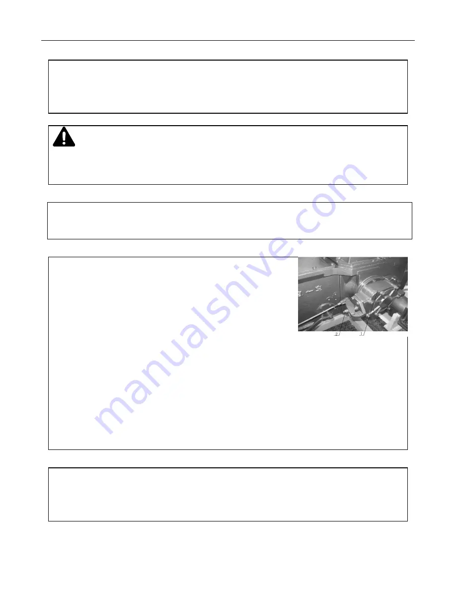
Figure 4-9 Brake Pedal Adjustment
1. Lock Nut 2. Adjustment Rod
Adjustment Method:
Loosen the lock nut (1) on the adjustment rod (2) and turn the rod.
The brake pedal free path will be decreased or increased depending on the direction you turn the rod.
The right and left pedal free path should be adjusted to be the same. The lock nut (1) should be tightened
after adjustment.
4.6.2 Right/Left Braking Force Adjustment
The braking force of the right and left brakes should be consistent. Usually when emergency braking
on a paved surface, the tire trace of the right and left drive wheels should be the same.
Adjustment Method
: Loosen the two lock nuts on the brake rod, adjust, and retighten the two nuts.
Summary of Contents for 82XTC
Page 53: ...Electrical Schematic 47...
Page 117: ...TD80 Serials TD824 1F461D19K...


