Side 5 of 16
Userguide CableTroll 210 March 2020
01021000/11/12/13
2. Technical description
2.1 General description
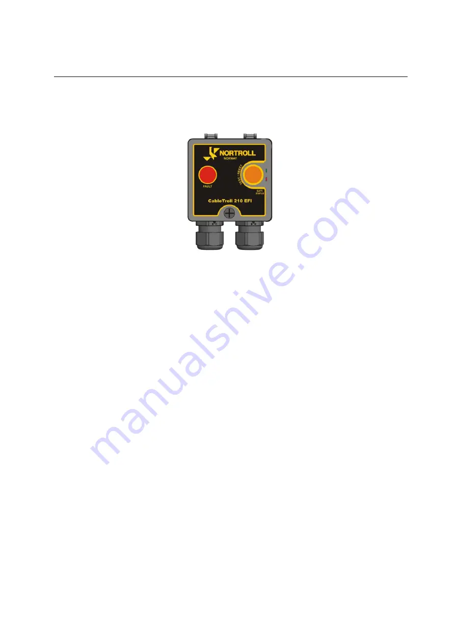
The indicator comprises one pcb cards mounted in an enclosure with hinched front cover
(consist of 3 LED
’s) for access to terminal blocks, battery and dip switches. Both control & signalling is
combined in one box.
Prod. Nr 01021000/11/12/13
2.2 Indication
One main high visibility red LED (visibility >10meters) for earth fault indication.
2 additional smaller LED
’s (Green & Red/Amber) for battery status indication.
2.3 Remote contact
Relay contacts (for remote signalling) for Earth fault and Low battery
Latched voltage free contact relay. One Normally Open (NO) and one Normally closed (NC)
Pulse relay may be available from factory on request
.
2.4 Rogowski coil/Current Transformer (CT)/ Earth-fault element
The indicator uses one direct type Rogowski coil for detection of earth faults only.
2.5 Housing
Housing designed for outdoor mounting.
2.6 Glands
Two cable glands gland are included with the indicator.
2.7 Resetting Indication options
Programmable timer (DIP Switch)
Automatic reset by voltage (230VAC) or from CT (imbalance
˃ 3A)
Supervisory Reset from SCADA (Immediate/2sec)
Manual reset by a push-button located on the front of the indicator.
2.8 Power Supply
Internal 3,6Ah/3,6V long life lithium battery for up to 10 years operation
2.9 NFC, Near Field Communication
The CT 210 has NFC for collecting info from the indicator such as Firmware version, Serial Number,
Programming/Dip-switch settings, battery status, fault counter and link to valid Mounting Instruction.


