Page 7
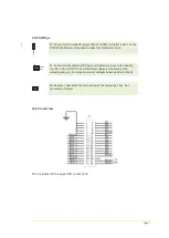
Link Settings
Lo
w
B
att
F1
Ext.DC
Batt.
F2
J8
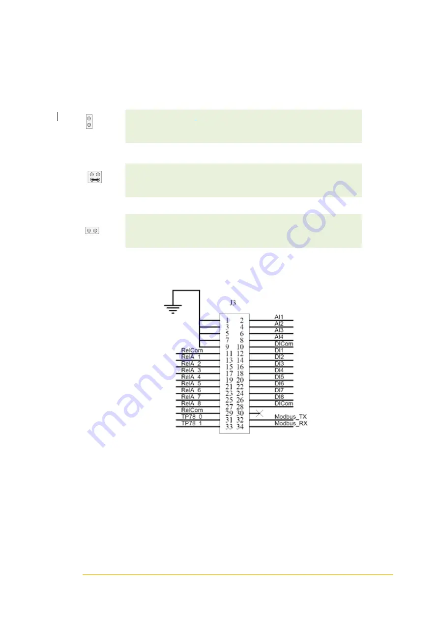
J3 pin overview
Pin 1 is located in the upper left corner of J3.
F1: Connects the Low
Battery signal from SLC-200+ to Digital Input 1 on the
NTM-20/25 Modem. Only used in repeaters. Default set open.
F2: Connects either External DC input or the Battery Input to the Analog
Input 4 on the first RTU-30 card. Battery voltage is monitored as the
default option. Ai_4 is setup to monitor voltages between 0V and 15Vdc.
F8: Activate / deactivate the termination of the twisted pair bus. Not
mounted as default.


