background image


Page 9 


generally works well on a window-ledge or positioned in a window or wall.  As a rule of 
thumb, the better the view the antenna has of the sky, the better the signal locks and a good 
continuous uninterrupted time signal is provided. 


TSU-25 can only be used together with RTU-30t. When more than one RTU-30t card is 
installed in the same rack, a Router Module (RTR-10) must be installed. 
 

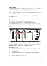
Running LED (green): 

LED flash once every 10 seconds as long as the TSU-25 is powered and the software runs OK. 
 

Sync-LED (yellow): 

The LED flashes every second when the GPS-unit is active. 
 

Status-LED (red): 

When the TSU-25 does not have a valid time, the Status LED will flash once a second. 
 

Normal operating condition:


The TSU will activate the GPS every 660s (11min) or 2500s (42min) dependent upon the 
measured temperature. When the interval expires the GPS will be activated and the Sync-LED 
will start flashing. The LED flashes until the clock is updated.  
 
Independent of this update, the TSU-25 sends out a time-sync message on the backplane 
bus. The RTU-30T cards that are placed on the same bus will receive this accurate time 
information and update the software clock that runs constantly on each individual RTU-30t 
card. 
This will give an accuracy of +/- 10ms on the time information sent from the RTU upon an 
event. 
 

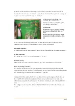
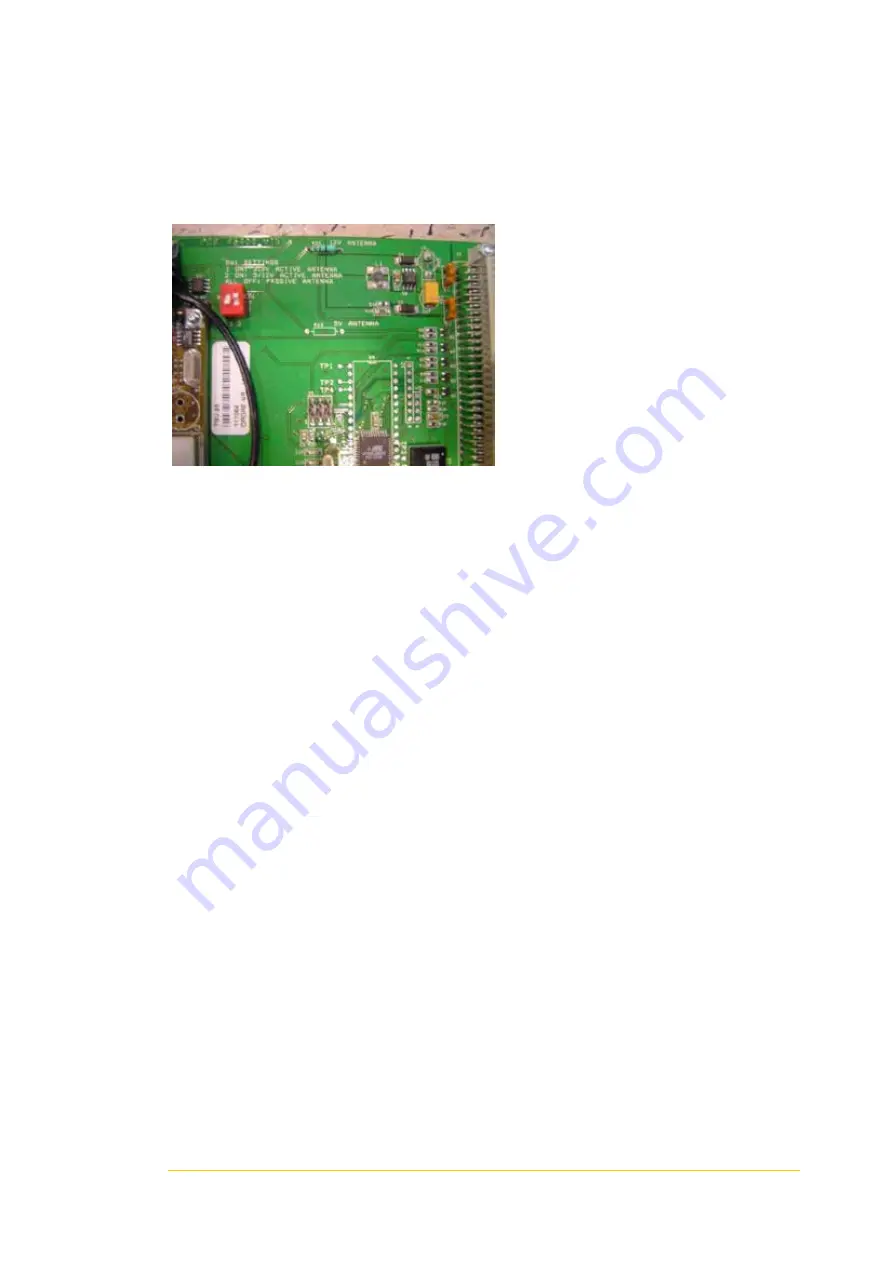
Different types of antennas are 

available. The default antenna is a 

3.3V active antenna, but other types 

of antennas can be used.’ 


IMPORTANT: 

Do NOT change any antenna settings 

without consulting NORTROLL AS 

first. 

Wrong setting can cause permanent 

damage to the GPS unit and the TSU-

25. 


Summary of Contents for ComTroll 230

Page 1: ...Page 1 ComTroll 230 ComTroll 230T ComTroll 230S User Manual...

Page 2: ...ERVICE NORTROLL AS RTU 30i LOCAL REMOTE OFF REMOTE CLOSE OPEN SERVICE RESET TX RX CLOSED OPEN SERVICE NORTROLL AS RTU 30i LOCAL OFF CLOSE OPEN SERVICE RESET TX RX CLOSED OPEN SERVICE NORTROLL AS RTU 3...

Page 3: ...230 REMOTE TERMINAL UNIT 4 COMMUNICATION 5 POWER SUPPLY 6 CONNECTIONS 6 Main backplane 06310a 6 Link Settings 7 J3 pin overview 7 J7 Bridge overview 8 COMTROLL 230T 8 Installing the TSU 25 8 COMTROLL...

Page 4: ...reactive power bus bar voltage load current and more Based on the RTU 30 Controller unit ComTroll 230 offers both local and remote control of the connected equipment ComTroll 230 can be connected to...

Page 5: ...al Unit can communicate with the central unit SCADA on different communication media The most commonly used is low power radio and fiber optics but the flexible communication platform can utilize almo...

Page 6: ...30 card Each additional RTU 30i card in a rack needs a separate backplane The RTU cards are tied together on the Local Bus Bridge Cable where also supply voltage is transferred to the next unit NORTRO...

Page 7: ...al Input 1 on the NTM 20 25 Modem Only used in repeaters Default set open F2 Connects either External DC input or the Battery Input to the Analog Input 4 on the first RTU 30 card Battery voltage is mo...

Page 8: ...substation can be precisely time tagged by the use of GPS Time Synchronization Unit TSU 25 The TSU25 utilizes the accurate time signal broadcasts from the GPS satellite network The TSU 25 has an integ...

Page 9: ...ondition The TSU will activate the GPS every 660s 11min or 2500s 42min dependent upon the measured temperature When the interval expires the GPS will be activated and the Sync LED will start flashing...

Page 10: ...ote worst case 7 sec every 24 hour period ComTroll 230S ComTroll 230S is a gateway that resides on the ComTroll Network and connects to Modbus devices over EIA 232 or EIA 485 The controller module RTU...

Page 11: ...03 0200 01 CRU 200 SPM Radio and modem without router module Product nr 03 0200 02 CRU 200 DC Radio and modem with router module Product nr 03 0030 50 RTU 30 Additional Modbus Object AMO Product nr 03...

Reviews: