background image


Page 10 


User Manual LineTroll R400D 

The visibility of the local flash will be reduced in this mode, but as the indicator will send all its 
alarms on GPRS and/or SMS anyway, the bright strobe flash is maybe not needed and 
therefore battery lift-time can be extended as a trade-off for visibility. 


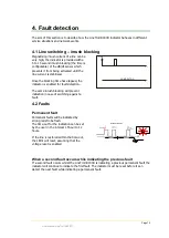
Permanent faults 

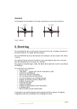
A permanent fault is defined as a fault where the line remains de-energized after tripping 

upon a fault. The time the indicator waits until it defines a fault as permanent can be 
configured in the range of 40 seconds to 300 seconds. 


Fast Auto
Reclosing

Last
Reclosing
Non-successful

Fault

40 to 300 sec

5 to 15 sec

SMS with ’Permanent 

Fault’

Permanent Fault


Transient faults 

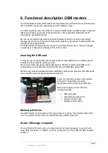
A transient fault is defined as a fault where the line is re-energized before the timeout of the 

permanent fault timer. The line must be energized longer than 15 to 30 seconds. 
 

Fast Auto
Reclosing

Fault

15/30 sec

SMS with ’Transient 

Fault’

Transient Fault


Sending GPRS/SMS alarms and messages 

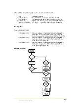
The built-in GSM modem is normally switched off to save battery power. The modem will be 
waked up as soon as the indicator have detected a fault and decided whether the fault is 
permanent or transient.  

 
The LineTroll R400D connects to the configured APN using a GPRS connection. If this 

connection fails and a “back

-

up recipient number” is set, the alarm will be sent to this number 

in an SMS instead. Two other SMS recipients is also possible to configure. 

 
After the unit have sent the GPRS data and/or SMS with the alarm message, the GSM modem 
remains powered for a configurable time to receive eventually messages sent to it. (Default 

2min). After that it goes back to sleep mode. 
 

Time-stamped events 

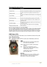
The LineTroll R400D have a built-in GPS and all events sent to the central will be time-
stamped with a highly accurate time and date. 
The time sent will be dependent upon whether the CB-trip criteria are ON or OFF: 


Summary of Contents for LineTrol R400D

Page 1: ...LineTroll R400D Pole Mounted Fault Passage Indicator with built in Mobile Data Communication SMS GPRS User Manual...

Page 2: ...to change without notice No parts of this documentation may be reproduced in any form by any means without the written permission of Nortroll AS Copyright 2018 Nortroll AS All rights reserved All Nort...

Page 3: ...SCHARGES 16 4 7 SETTING THE TRIP LEVEL 17 4 8 SENSITIVITY 17 5 EVENT LOG 19 6 FUNCTIONAL DESCRIPTION GSM MODEM 20 INSERTING THE SIM CARD 20 MANUAL ACTIVATION 20 ALARM MESSAGE RECIPIENTS 20 Sending SMS...

Page 4: ...nality from E is amended into the D version Please note the importance of using the correct configuration template matching the firmware in your field device when configuring the device using NetTroll...

Page 5: ...r be possible to give an accurate distance as it will be very individual The lens of the indicator can be turned to either side for optimal visibility The indicator does also have separate indications...

Page 6: ...ppen before it starts indicating a fault and send the alarm to the control center The general sequence is as follows ref fig 2 1 The line should be energised for at least 5 seconds Inrush blocking tim...

Page 7: ...level Figure 3 magnetic field It is important to notice that the indicator measure a B field which is a product of the current flowing in the feeder The trip setting values for short circuit and earth...

Page 8: ...and LineTroll R400D can detect PtG faults as low as 2A 2 3 Operation Installation and mounting The indicator must be calibrated to the normal line conditions during the installation of the device Thi...

Page 9: ...ation not dependent on de energised line 2 4 Indication LED indication The LineTroll R400D is equipped with a separate indication board in the bottom lens of the indicator D1 D2 D3 D4 Figure 5 LED ind...

Page 10: ...an 15 to 30 seconds Fast Auto Reclosing Fault 15 30 sec SMS with Transient Fault Transient Fault Sending GPRS SMS alarms and messages The built in GSM modem is normally switched off to save battery po...

Page 11: ...nergized until the indicator is reset can be set The following voltage reset delay selections can be made 5s 10s 15s 20s 25s or 30s 2 Automatic timer reset The timer reset can be set to any value betw...

Page 12: ...ctionalizing switches NorTroll s actuators for sectionalizing switches 3 1 Suitable networks The LineTroll R400D fault indicator can be used in the following networks 6 132kV distribution networks Rad...

Page 13: ...s 11kV min 25 meters Figure 7 mounting restrictions When LineTroll R400D is mounted in fused lines special percussions should be taken See section 4 4 for details about fused lines The indicator shoul...

Page 14: ...in case of switching against a fault t t LINE I NO INDICAT ION 4 2 Faults Permanent fault Permanent faults will be indicated by strong red strobe flash The time out for the indication can be set by t...

Page 15: ...eset feature must be switched ON if the indicator shall reset upon re energizing of the feeder The reset time is configurable 5 to 30 sec 4 4 Fused lines When the circuit breaker trip criteria are swi...

Page 16: ...icator is below the pre set trip level for PtG faults in order to avoid the indicator incorrectly activating behind the fault In general capacitive discharge currents can be neglected in solidly earth...

Page 17: ...setting of trip level especially with regards to capacitive discharge currents Basic rules for setting the trip level IT is To avoid incorrect detection because of capacitive current from the network...

Page 18: ...e indicator requires that two conditions are satisfied in order to detect a short circuit fault 1 The relative increase dB is greater than a certain level 50 100 or 200 2 The absolute dB T is greater...

Page 19: ...ed NetLogger Please find details about reading the log in the User Manual for NetLogger The events that can be logged are Power up reset Temperature Logged every time the temperature is read Connectio...

Page 20: ...that is most economic and suitable for your system please contact your local network service provider We do not recommend using prepaid subscriptions We also recommend disabling voice communication o...

Page 21: ...number only in if GPRS Connection is used as primary channel and this channel fails SMS Recipient 2 If a number is set in this parameter location the alarm or message is always sent in SMS to this nu...

Page 22: ...ever this message will appear when the indicator has detected a fault and the alarm message shall be sent even if this message is switched OFF Also when the indicator detects a de energized line and a...

Page 23: ...MM Month DD Day hh Hours mm Minutes ss Seconds tt Milliseconds Tx When sending a message from NetTroll e g status request a Tx number is added in the message The Tx number send from the indicator in t...

Page 24: ...usage of the message filter the secondary number can be maintenance central and should keep track on heartbeat messages low battery boot messages etc whereas the primary e g the main SCADA should rec...

Page 25: ...having sent an alarm or a heartbeat message Setting polling up time Defines the period the GSM modem is connected to the GSM network after having done the regular polling sequence and checked the GSM...

Page 26: ...between 10 and 3000 Passwords All messages sent to the device must contain a password corresponding to the programmed password It is also a separate configuration password which will lock all configur...

Page 27: ...o configure the unit A detailed description of the configuration properties is given in the Configuration Manual for the RIS system This manual covers all possible methods of configuration The most im...

Page 28: ...The LineTroll R400D can be fitted with different types and number of batteries By default the LineTroll R400D is equipped with three KBB 20 batteries which gives a total capacity of 39Ah In the config...

Page 29: ...ely From SCADA or NetTroll or FDP 10 hand held unit from ground Indication 1 Green LED for transient faults Can be switched off High visibility red strobe flash for permanent fault Low battery indicat...

Page 30: ...Page 30 User Manual LineTroll R400D 11 Dimensions 98 78 380 11 Figure 11 dimensions...

Page 31: ...ypically 3 to 5 meters below the conductors 3 5 meter If the bracket has been mounted on the pole with either screws or cable ties with the indicator removed from the bracket the indicator housing can...

Page 32: ...re than 1 meters below the indicator while the LED s are flashing 3 After approx 9 seconds the adaption to the line conditions will start The LED s will be OFF during the adaption 4 After the adaption...

Reviews: