Page 17
User Manual LineTroll R400D
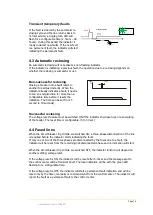
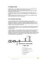
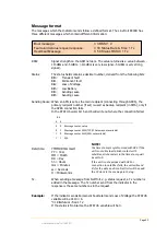
Calculation example (resistor earthed neutral):
L
OH
= L1+L2= 20km
L
C
= 1km PEX cable
U = 22kV
𝐼
𝐶𝐴𝑃
=
𝑈 ∙ 𝐿
𝑂𝐻
𝑇
+
𝑈 ∙ 𝐿
𝐶
𝐾
𝐼
𝐶𝐴𝑃
=
22∙20
300
+
22∙1
5
= 5,9 A
In order to avoid activation of LineTroll R400D units installed downstream of the location in the
above example, the trip level for PtG faults must be set to a higher value than 5,9A.
The following criteria have to be met:
𝑰
𝒄𝒂𝒑
< 𝑰
𝒕
I
Cap
= Capacitive current down-streams of the indicator
I
t
= Sensitivity for Earth Fault (PtG Trip level)
4.7 Setting the trip level
In networks with the feeding transformers neutral isolated from the earth, earth fault current
normally is low.
In such network it is important to do a thorough analysis of the network to find the correct
installation and setting of trip level, especially with regards to capacitive discharge currents.
Basic rules for setting the trip level
I
T
is:
To avoid incorrect detection because of capacitive current from the network down-stream of
the indicator:
I
C
<
I
T
: where
I
C
= capacitive current down-streams of the indicator.
To ensure correct detection the following has to be met:
I
T
< I
PTG
- I
C
where
I
PTG
= the networks total Earth Fault current.
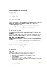
These two rules can be summarised as follows:
I
C
< I
T
< I
PTG
- I
C
4.8 Sensitivity
Earth faults
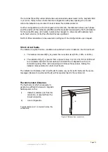
LineTroll R400D monitors the resulting magnetic field below the conductors.
The sensitivity for earth faults is a function of the following variables:
✓
The trip level set on the indicator (2, 4, 7, 15, 20, 30, 40 or 50 [A])
✓
The line configuration
✓
The distance between each phase and the fault indicator
✓
The load current at the time of the installation (load current will during fault detection
be neglected by the LCC feature).

