background image

- 10 -

8. W

IRING

 D

IAGRAMS

 (

CONT

D

)

BL

W

Open: 93.3°C

MRTP 1

MRTP 2

24 VAC
COMMON OUT

24 VAC
POWER OUT

CALL FOR FAN

CALL FOR
HEAT 1

CALL FOR
HEAT 2

BL

BK

HEAT INDICATOR 

C

G

R

W1

W2

TB

BL

BL

Season Select

BK

Class 2 Transformer

Pri: 240 V 60 Hz

Sec: 24 V 60 Hz 40 VA

Y

T

Y

Y

BK

R

Y

27 kW 240 VAC

Single phase

W

BL

BL

BK

Y

BK

BK

BL

R

BK

R

BK

Recirculation

Mode

K1 24V

1

5

2

3

6

4

K2 240V

1

5

2

3

6

4

240

VAC

NC

C

24V

AC

BL

BK

BK

BK

BK

BL

R1

M6

M5

24V

AC

BL

M2

M1

M4

M3

24V

AC

BL

BL

50 A

A2

A1

BK

BK

BK

50 A

BL

R2

M4

M3

24V

AC

BL

M2

M1

50 A

R3

M2

M1

24V

AC

BK

BK

BK

BK

HEAT 2

E

ARTP

R

HEAT 3

E

ARTP

R

HEAT 1

E

ARTP

R

HEAT 4

E

ARTP

R

HEAT 5

E

ARTP

R

HEAT 6

E

ARTP

R

O

BK

R

L1

L2

N

G

M

B3

50 A

B2

50 A

B1

50 A

BK

BK

BK

R

R

BK

BK

R

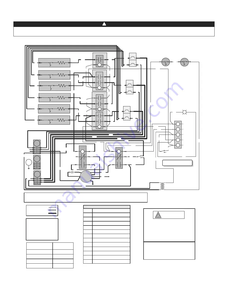
1. If any of the original wire, as supplied, must 
be replaced, use the same equivalent wire. 
Wiring must comply with applicable codes, 
ordinances and regulations.

2. Field wiring must comply with applicable 
codes, ordinances and regulations. Use only 
Class 1 wiring inside furnace compartments.

Critical characteristic

Line voltage wiring:
UL AWM 1015, 600V, 105°C, VW-1, 8 AWG;  

CSA TEW 600V, 105°C, FT1, 8 AWG and 12 AWG.

Low voltage wiring: 
same  ratings as high voltage except 18 AWG. 

HI

MED-HIGH

MED-LOW

LOW

FAN MOTOR SPEED

BLACK

BLUE

YELLOW

RED

COLOR

LEGEND

C

E

R

K

MRTP

HEAT

L1, L2

Capacitor

Heating Element

Time Delay Relay

Fan Relay 

Auto-Reset Thermal Protector

Manual-Reset Thermal Protector

240 V Line Supply

WIRING COLOR CODE

 BK 

BLACK

 BL 

BLUE

 O 

ORANGE

 R 

RED

 W 

WHITE

 Y 

YELLOW

ARTP

M

TB

T

N

Fan Motor

Terminal Block

Transformer Class 2

Heat

Neutral

B

Breaker

Low power
High power
High power 8 AWG

For the use of a two-stage thermostat or an outdoor thermostat, connect between W1 and W2.
Make sure that the Season Select switch is set to “Mild” position.

R

BK

BK

R

R

FE0063A

UL AWM 1015/1230, 600V, 105°C, VW-1, 12 AWG;  

WARNING

Risk of electric shock. Disconnect power before installation, servicing, maintenance or field wiring. Replace all panels 
before operating. Failure to do so can result in electric shock causing severe injuries or death.

 21B27MS 

Model

Summary of Contents for 21B10M

Page 1: ...N AND USER MANUAL IMPORTANT READ AND SAVE THESE INSTRUCTIONS MODELS 21B10M 21B15M 21B18M 21B20M 21B25M 21B27MS 83B13 83B24 AND 83B27 M A DE IN CANA D A F A B R I Q U AU CA N A D A NORTRON Sherbrooke Q...

Page 2: ...ture furnace failure thus voiding the warranty Do not block the combustion air openings in the furnace Any blockage will result in improper overheat situation and may result in a fire hazard and or ca...

Page 3: ...ERED FURNACE HUMIDIFIERS 7 7 4 INTERLOCK CONNECTION 7 8 WIRING DIAGRAMS 8 11 9 SERVICE PARTS 12 10 MAINTENANCE 13 11 TROUBLESHOOTING 13 12 WARRANTY 14 1 DIMENSIONS FK0004A FRONT VIEW RIGHT SIDE VIEW R...

Page 4: ...x 203 mm 23 41 LOW 663 21B15M 15 51228 67 1 3 24 43 MED LOW 814 21B18M 18 61473 77 1 3 27 49 MED LOW 814 21B20M 20 68304 86 1 3 33 59 MED LOW 814 21B25M 25 85379 107 1 3 37 67 MED LOW 814 21B27MS 27...

Page 5: ...s are turned on by the thermostat OFF The blower motor will operate in the standard heating mode controlled by the thermostat MILD During spring and fall you may not require full heating capacity to m...

Page 6: ...of a floor opening 14 x 14 362 mm x 362 mm The duct system must be designed so that the external static pressure of the system does not exceed the maximum external static pressure of 0 50 W C 125 Pa S...

Page 7: ...ummer directing all air flow through the coil In winter the damper would be open to allow air to bypass the coil Typical air conditioning field wiring connections are shown in the diagram at right FUR...

Page 8: ...ing same ratings as high voltage except 18 AWG HI MED HIGH MED LOW LOW FAN MOTOR SPEED BLACK BLUE YELLOW RED COLOR LEGEND C E R K MRTP HEAT L1 L2 Capacitor Heating Element Time Delay Relay Fan Relay A...

Page 9: ...he original wire as supplied must be replaced use the same equivalent wire Wiring must comply with applicable codes ordinances and regulations 2 Field wiring must comply with applicable codes ordinanc...

Page 10: ...rdinances and regulations Use only Class 1 wiring inside furnace compartments Critical characteristic Line voltage wiring UL AWM 1015 600V 105 C VW 1 8 AWG CSA TEW 600V 105 C FT1 8 AWG and 12 AWG Low...

Page 11: ...use the same equivalent wire Wiring must comply with applicable codes ordinances and regulations 2 Field wiring must comply with applicable codes ordinances and regulations Use only Class 1 wiring ins...

Page 12: ...57 12 6 5 37 21 9 DQ 5HOD QRW LQ 0 9 DQ 5HOD 7UDQVIRUPHU 9 ORZHU KHHO PP PP IRU ORZHU 0RWRU 3 9 IRU 06 0RWRU 3 9 IRU 0 0 0 0 DQG 0 0RWRU 3 9 IRU 6HULHV OHPHQW VVHPEO 9 OHPHQW VVHPEO 9 OHPHQW VVHPEO 9...

Page 13: ...N MODE switch open contact Bottom sequencer 4 Motor going on and off in short cycles or in too long cycles Heat anticipator in thermostat incorrectly set or may be defective 5 The thermostat must be s...

Reviews: