background image

4135 English, rev 3


11

service and MainTenance

Installation

The machine must be placed on firm ground e.g. cemented floor. The ground must be level in order to 

avoid tensions in the machine when fixing it to the floor.
Check that the motor is branched to the right voltage. Also check the direction of rotation. Plates with 

“Forward” and “Reverse” are mounted on the protection cover of the foot switch. 
If the machine is equipped with motor powered setting of the bending roll and/or  the lower roll also 

check the voltage and oil level here.

Maintenance

The machine is delivered with greased bearings for about 200 hours’ continuous duty. After this period it 

should be lubricated with ball bearing grease of good quality, e.g. Esso Multi purpose grease H or equiv-

alent. All rolls and worm gears are mounted on needle and ball bearings and therefore recommended 

grease should be used. Guides for the roll bearing box as well as sleeves for the upper roll and cone 

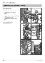
bending device to be lubricated when required. Grease lubs, see grease chart.
The gearbox is lifetime lubricated and doesn’t need any regular inspection. Should there be any leakage, 

please check oil level and refill if necessary.

Daily check

•  Brake function of the motor
•  All emergency stop functions

Parallelism of the rolls

Check that all rolls are parallel. If adjustment is necessary proceed as follows:

Between upper and  lower rolls:
•  Crank up the lower roll to its highest position.
•  Loosen the two nuts blocking the wedge on the transmission side.
•  Adjust by means of the wedge until the distance between the upper and lower rolls are the same in 

both ends

•  Lock the wedge by means of the nuts.

Between upper and bending rolls:
•  Press the bending roll by means of the lever up to its highest position.
•  Loosen the screw of the cam disk.
•  Adjust  until the distance between the upper and bending rolls is the same at both ends.
•  Retighten the screw against the cam disk . 

Summary of Contents for 4135

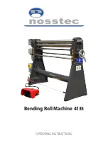
Page 1: ...Bending Roll Machine 4135 Operating Instructions...

Page 2: ......

Page 3: ...and stickers 14 Dismantling of bending roll machine 15 Spare parts 16 Declaration of conformity 18 Contact information See back Note We reserve the right to alter specifications without prior notice...

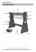
Page 4: ...wer roll Stand slip collar side Pull out sleeve Hand wheel for lower roll Lever for bending roll Main components Front side Foot switch Disclaimer The machine pictured on this page is not necessarily...

Page 5: ...t the operation until the workpiece has got the desired shape Swing out the top roll and remove the workpiece Swing back the top roll into its initial position At the maximum operating length and shee...

Page 6: ...fting instructions This machine must be lifted by truck as long as it is packed in a crate or a wooden case When lifting it from the packing to the permanent working site an ap proved lifting device t...

Page 7: ...atisfactory The floor must be clean dry and free from oil and grease spots Never use easily inflammable material close to the machine Dirty working sites increase the risk of accidents Position of top...

Page 8: ...safe place The instruction manual contains important information that besides the safety information also give important information regarding operation service maintenance etc Modification of the ma...

Page 9: ...If the machine must be dismantled completely or partly contact your foreman Protective clothing Important Never use gloves when bending as this consider ably increases the risk of getting pinched bet...

Page 10: ...l that the operator has got the necessary information regard ing the safety of the machine as well as the special risks involved with this type of machine If the machine is not used in the proper way...

Page 11: ...ease should be used Guides for the roll bearing box as well as sleeves for the upper roll and cone bending device to be lubricated when required Grease lubs see grease chart The gearbox is lifetime lu...

Page 12: ...re in total 8 lubrication points 1 1 grease nipple in each bearing housing 2 1 grease nipple in the gear housing 3 1 grease nipple on the back side of each stand level with the axle 4 1 grease nipple...

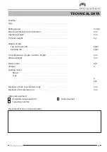
Page 13: ...of rolls Top and lower rolls kg m Bending roll kg m Total dimensions length width height mm Working height mm Motor rating kW Voltage V Feeding motor Brand Type V kW Diameter of rolls top and lower ro...

Page 14: ...ckground white text Blue background white text MAIN SWITCH MUST BE DISCONNECTED FOR ALL TYPES OF SERVICE AND MAINTENANCE ONLY TRAINED STAFF MAY HANDLE THIS MACHINE Never run the machine with the top r...

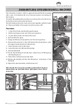
Page 15: ...3 Loosen the four bolts and remove the cover 4 Dismount the two gears 5 Swing out the top roll and pull it out of the worm gear box 6 Dismount the tube bar at the front bottom stand and place a suita...

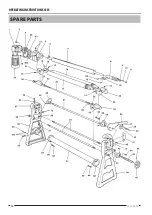
Page 16: ...Operating Instructions 4135 16 2013 05 23 SPARE PARTS...

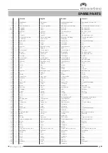
Page 17: ...28 1 Mutter Nut Mutter Ecrou 29 1 Stoppskruv Stop screw Stellschraube Vis d arr t 30 1 Excenter Eccentric Exzenter Excentrique 31 1 Axel Axle Achse Axe 32 1 Sp nnstift Roll pin Spannstift Goupille de...

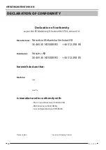
Page 18: ...anufacturer Nossebro Mekaniska Verkstad AB SE 465 30 NOSSEBRO 46 512 298 80 Distributor Nosstec AB SE 465 30 NOSSEBRO 46 512 298 85 herewith declare that Machine Type Serial No is manufactured in conf...

Page 19: ......

Page 20: ...41 39 Alings s SWEDEN Tel 46 0 512 298 85 Fax 46 0 512 298 89 E mail info nosstec se For copyright reasons all reproduction and copying of the texts tables and illustrations within this manual is proh...

Reviews: