background image

4135 English, rev 3


17

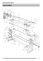
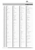
spare parTs

Svenska

English

Deutsch

Francais

1

1

Snäckväxel

Worm gear

Schneckengetriebe

Engrenage à vis sans fin

2

4

Skruv

Screw

Schraube

Vis

3

1

Lock för växelhus

Cover for gearbox

Abdeckung für Getriebe

Couvercle de boîte de vitesses

4:01

1

Kugghjul

Gear

Zahnrad

Roue dentée

4:02

1

Kugghjul

Gear

Zahnrad

Roue dentée

5

1

Växelhus

Gearbox

Getriebegehäuse

Boîte de vitesse

6

1

Kil

Wedge

Keil

Coin

7

1

Övervals

Top roll

Oberwalze

Rouleau supérieur

8

1

Hylsa med styrning

Sleeve with guide

Buchse mit Führung

Douille avec guide

9

1

Ändbricka

End washer

Endplatte

Disque

10

1

Spännstift

Roll pin

Spannstift

Goupille de serrage

11

1

Skruv

Screw

Schraube

Vis

12

4

Skruv

Screw

Schraube

Vis

13

1

Lagerhus

Bearing housing

Lagergehäuse

Boîte de palier

14

1

Kil

Wedge

Keil

Coin

15

8

Smörjnippel

Grease nipple

Schmiernippel

Graisseur

16

1

Böjvals

Bending roll

Biegewalze

Rouleau arriére

17

1

Undervals

Lower roll

Unterwalze

Rouleau inférieur

18

1

Styrning

Guide

Führungen

Guide

19

1

Smörjnippel

Grease nipple

Schmiernippel

Graisseur

20

1

Lagerhus

Bearing housing

Lagergehäuse

Boîte de palier

21

1

Lagerhus

Bearing housing

Lagergehäuse

Boîte de palier

22

1

Kil

Wedge

Keil

Coin

23

6

Mutter

Nut

Mutter

Ecrou

24

1

Axel

Axle

Achse

Axe

25

1

Ok

Support

Stütze

Support

26

1

Lagerhus

Bearing housing

Lagergehäuse

Boîte de palier

27

1

Kil

Wedge

Keil

Coin

28

1

Mutter

Nut

Mutter

Ecrou

29

1

Stoppskruv

Stop screw

Stellschraube

Vis d’arrêt

30

1

Excenter

Eccentric

Exzenter

Excentrique

31

1

Axel

Axle

Achse

Axe

32

1

Spännstift

Roll pin

Spannstift

Goupille de serrage

33

1

Skruv

Screw

Schraube

Vis

34

1

Bricka

Washer

Scheibe

Rondelle

35

1

Kamskiva

Cam

Kamscheibe

Disque à came

36

1

Handtag

Handle

Griff

Poignée

37

1

Fjäder

Spring

Feder

Ressort

38

1

Bricka

Washer

Scheibe

Rondelle

39

1

Skruv

Screw

Schraube

Vis

40

1

Spärr

Lock

Verriegelungsgriff

Poignée de verrouillage

41

1

Kuggsegment

Cog segment

Zahnsegment

Segment denté

42

1

Skruv

Screw

Schraube

Vis

43

2

Flänsmutter

Flange nut

Flanschmutter

Écrou à embase

44

1

Skruv

Screw

Schraube

Vis

45

2

Skruv

Screw

Schraube

Vis

46

1

Spännstift

Roll pin

Spannstift

Goupille de serrage

47

1

Ratt

Wheel

Handrad

Volant

48

2

Gavel underdel

Side, lower

Giebel, unten

Bâti partie inférieure

49

8

Bricka

Washer

Scheibe

Rondelle

50

8

Skruv

Screw

Schraube

Vis

51

1

Rörstag

Pipe strut

Rohrstrebe

Support tubulaire

52

1

Gavel utsvängbar sida

Side, openable side

Giebel, Nebentüren

Bâti côté pivotant

53

1

Motor

Motor

Motor

Moteur

54

2

Stag

Strut

Strebe

Support

55

1

Skruv

Screw

Schraube

Vis

56

1

Mutter

Nut

Mutter

Ecrou

57

1

Gavel transmissionssida

Side, transmission side

Giebel, Transmissionseite

Bâti côté de transmission

58

1

Axelsäkring

Axle lock

Achssperre

Arrêt d’axe

59

4

Mutter

Nut

Mutter

Ecrou

60

2

Skruv

Screw

Schraube

Vis

61

4

Skruv

Screw

Schraube

Vis

62

1

Fläns

Flange

Flansch

Bride

63

1

Fläns

Flange

Flansch

Bride

64

2

Klammer

Clip

Klammer

Crampon

65

2

Skruv

Screw

Schraube

Vis

Summary of Contents for 4135

Page 1: ...Bending Roll Machine 4135 Operating Instructions...

Page 2: ......

Page 3: ...and stickers 14 Dismantling of bending roll machine 15 Spare parts 16 Declaration of conformity 18 Contact information See back Note We reserve the right to alter specifications without prior notice...

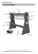
Page 4: ...wer roll Stand slip collar side Pull out sleeve Hand wheel for lower roll Lever for bending roll Main components Front side Foot switch Disclaimer The machine pictured on this page is not necessarily...

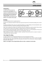
Page 5: ...t the operation until the workpiece has got the desired shape Swing out the top roll and remove the workpiece Swing back the top roll into its initial position At the maximum operating length and shee...

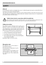
Page 6: ...fting instructions This machine must be lifted by truck as long as it is packed in a crate or a wooden case When lifting it from the packing to the permanent working site an ap proved lifting device t...

Page 7: ...atisfactory The floor must be clean dry and free from oil and grease spots Never use easily inflammable material close to the machine Dirty working sites increase the risk of accidents Position of top...

Page 8: ...safe place The instruction manual contains important information that besides the safety information also give important information regarding operation service maintenance etc Modification of the ma...

Page 9: ...If the machine must be dismantled completely or partly contact your foreman Protective clothing Important Never use gloves when bending as this consider ably increases the risk of getting pinched bet...

Page 10: ...l that the operator has got the necessary information regard ing the safety of the machine as well as the special risks involved with this type of machine If the machine is not used in the proper way...

Page 11: ...ease should be used Guides for the roll bearing box as well as sleeves for the upper roll and cone bending device to be lubricated when required Grease lubs see grease chart The gearbox is lifetime lu...

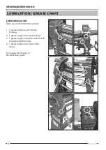
Page 12: ...re in total 8 lubrication points 1 1 grease nipple in each bearing housing 2 1 grease nipple in the gear housing 3 1 grease nipple on the back side of each stand level with the axle 4 1 grease nipple...

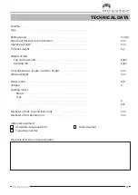
Page 13: ...of rolls Top and lower rolls kg m Bending roll kg m Total dimensions length width height mm Working height mm Motor rating kW Voltage V Feeding motor Brand Type V kW Diameter of rolls top and lower ro...

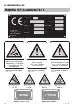
Page 14: ...ckground white text Blue background white text MAIN SWITCH MUST BE DISCONNECTED FOR ALL TYPES OF SERVICE AND MAINTENANCE ONLY TRAINED STAFF MAY HANDLE THIS MACHINE Never run the machine with the top r...

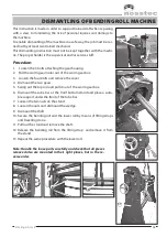
Page 15: ...3 Loosen the four bolts and remove the cover 4 Dismount the two gears 5 Swing out the top roll and pull it out of the worm gear box 6 Dismount the tube bar at the front bottom stand and place a suita...

Page 16: ...Operating Instructions 4135 16 2013 05 23 SPARE PARTS...

Page 17: ...28 1 Mutter Nut Mutter Ecrou 29 1 Stoppskruv Stop screw Stellschraube Vis d arr t 30 1 Excenter Eccentric Exzenter Excentrique 31 1 Axel Axle Achse Axe 32 1 Sp nnstift Roll pin Spannstift Goupille de...

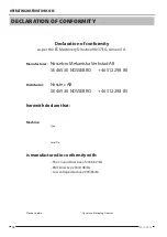
Page 18: ...anufacturer Nossebro Mekaniska Verkstad AB SE 465 30 NOSSEBRO 46 512 298 80 Distributor Nosstec AB SE 465 30 NOSSEBRO 46 512 298 85 herewith declare that Machine Type Serial No is manufactured in conf...

Page 19: ......

Page 20: ...41 39 Alings s SWEDEN Tel 46 0 512 298 85 Fax 46 0 512 298 89 E mail info nosstec se For copyright reasons all reproduction and copying of the texts tables and illustrations within this manual is proh...

Reviews: