background image

E

N

G

LI

S

H

9

INSTALLING THE COUPLER/REGULATOR

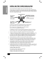
Attach the side spout of the regulator to your CO2 tank. Tighten with wrench.

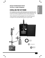
Attach the loose end of the Tap Tower hose line to the top spout of the coupler and secure 

with a hose clamp. Using the CO2 Hose, attach one end of hose to the bottom output of the 

regulator and secure with a hose clamp. Use the third clamp to connect the other end of the 

hose to the side output of the coupler. 

Use the screw in the center of the regulator to adjust the output pressure. 

When the desired pressure is reached spin the nut to lock in place. 

When the pressure is at the appropriate level, use the tank band 

to fix the CO2 tank to the inside of the kegorator. 

The Regulator works the CO2 Tank and measures PSI (pounds per square inch), as well as 

the volume of the CO2 gas in the cylinder. Set output pressure gauge between 8-12 PSI.

1. 

Close the shut off valve on the regulator, and open the CO2 tank valve completely. 

2. 

If needed, twist the locking nut loose so that the screw can be adjusted. Unlock screw using 

a screwdriver or by hand. Slowly turn the regulator adjustment screw until the desired 

pressure is shown on the output pressure gauge (8-12 PSI). Turning clockwise will increase 

the output pressure, and turning counter-clockwise will decrease the output pressure. 

3. 

Once desired pressure is reached, re-lock the nut with a wrench or by hand.

4. 

Open the CO2 shut-off valve on the regulator to allow gas flow from the regulator to the 

keg coupler. You will hear the keg pressurizing. The output needle will drop momentarily 

until the pressure has equalized. Then the needle will return to the point you set it at.

5. 

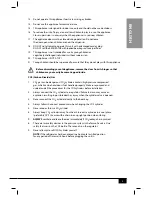
The keg coupler is designed with a pressure relief valve (PRV). Pull the ring on the 

PRV briefly to allow gas to vent. This will permit gas to flow through the regulator 

and help obtain a more accurate reading on the output pressure gauge.

6. 

Re-check the output pressure on the regulator, and if necessary re-adjust using step #2 until 

the desired pressure is shown. It is always wise to follow up any adjustment to the regulator 

with a brief pull of the PRV ring to ensure an accurate output reading. 


Location of Temperature Control

The temperature control is located in the upper right-

hand corner in the front of the  kegorator

.

Settings are min, normal, max and super cold. 

Pressure Relief Valve

Tank Pressure 

Gauge

 (0-

3000 PSI) for 

measuring PSI 

of CO2 in tank. 

Output Pressure Gauge


(0-60 PSI) for measuring PSI 

of CO2 outflow from Tank 

to Keg  

(8-12 PSI recommended).

Screw 

adjusts the 

output pressure. 

CO2 Shut Off 

Valve 

(shown in 

open position)


Summary of Contents for KEG7000SS

Page 1: ...All products are trademarks of Nostalgia Products Group LLC Worldwide design utility patented or patents pending 2012 Nostalgia Products Group LLC www nostalgiaelectrics com rev 08 22 13 2013 ...

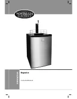
Page 2: ...KEG7000SS Kegorator Instruction Manual ...

Page 3: ......

Page 4: ...RANTY 13 SAFETY Appliance Specifications 115V 60Hz 1 47A max amps 6A UL Approved Your safety and the safety of others is very important We have provided many important safety messages in this manual and on your appliance Always read and obey all safety messages This is the safety alert symbol This symbol alerts you to potential hazards that can kill or hurt you and others All safety messages will ...

Page 5: ...bly instructions in this manual before it is used See the Parts Assembly section for more details 3 This appliance must be connected to a proper electrical outlet with the correct electrical supply 4 Proper grounding must be ensured to reduce the risk of shock and or fire DO NOT cut or remove the grounding plug If you do not have a three prong outlet in the wall have a certified electrician instal...

Page 6: ...become trapped inside CO2 Carbon Dioxide Gas 1 CO2 gas can be dangerous CO2 cylinders contain high pressure compressed gas which can be hazardous if not handled properly Make sure you read and understand all the procedures for the CO2 cylinders before installation 2 Always connect the CO2 cylinder to a regulator Failure to do so may cause an explosion resulting in possible death or injury when the...

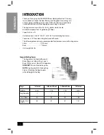
Page 7: ...s L 28 75 x W 21 x H 31 25 not including tap tower Tap tower is 15 from base to highest point of handle The following dimensions are recommended for clearances around the kegorator Sides 19 mm Back 1 25 mm Unit weight 86 lbs Compatible Keg Types The kegorator can hold either one 6 Barrel Keg one Barrel Short one Barrel Slim or one Barrel This kegorator DOES NOT fit non standard keg sizes NOTE Keg ...

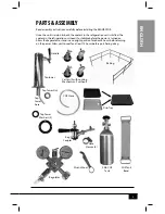
Page 8: ...s to stabilize before the power is turned on Allow the kegorator to stand in an upright position for about 8 hours before turning on the power Allow unit to cool for at least 12 hours before purchasing a keg CO2 Tank Band 2 5lb CO2 Tank Keg Coupler Regulator Tap Tower Washers 2 Railing Tap tower Handle CO2 Hose Tap Tower Nut Casters 2 with Locking Mechanism 2 without Drip Tray Hose Clamps 3 Tap to...

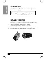
Page 9: ...cking Casters should be fastened at the front end of the unit 1 Empty the inside of the cabinet completely and lay the kegorator down on its back We recommend that you place a piece of cardboard or cloth underneath the cabinet to prevent dents or scratches 2 Insert the Casters into the holes on the bottom corners of the cabinet Tighten each Caster 3 Once all four Casters have been tightened stand ...

Page 10: ... the washer with the holes in the kegeorator and those in the base of the Tap Tower Using the four screws and nuts provided attach the Tap Tower to the top of the kegorator Slide the smaller rubber washer B up the Tap Tower hose then the large nut Screw in place until about an inch of the threaded end sticks out in the main compartment of the kegorator Attach the handle of the Tap Tower by twistin...

Page 11: ... clockwise will increase the output pressure and turning counter clockwise will decrease the output pressure 3 Once desired pressure is reached re lock the nut with a wrench or by hand 4 Open the CO2 shut off valve on the regulator to allow gas flow from the regulator to the keg coupler You will hear the keg pressurizing The output needle will drop momentarily until the pressure has equalized Then...

Page 12: ...ion Fig 4 This will open the beer and CO2 gas valves The Keg is now tapped HOWTO OPERATE Follow the steps below to dispense beer 1 Make sure that the kegorator is plugged in properly to a 120V 60Hz 15 Amps grounded AC outlet 2 Place the drip tray under the beer faucet to avoid messes from excess beer 3 Open the beer faucet by pulling the tap towards you to dispense the beer If for any reason the b...

Page 13: ...eep it in a location where there is proper air circulation and electrical outlets Choose a location where the kegorator will be away from heat and will not be exposed to direct sunlight Foamy Beer Follow these steps to prevent foamy beer Confirm the beer lines are not kinked and are clean To prevent foamy beer you may need to bring down your pressure even if it is below the recommended 8 12 PSI Pu...

Page 14: ... any excess beer that is trapped inside helping to prevent any bacteria or mold that could accumulate inside Follow the guidelines below to care for your kegorator when not in use Please adjust the temperature gauge to MIN in colder environments because this unit does not self defrost and ice may build up inside the unit The temperature control is located in the upper right hand corner Always rins...

Page 15: ...90 days of purchase we will repair or replace the unit at our option Our pledge does not apply to damages caused by shipping mishandling or unit being dropped A product deemed defective either from manufacturing or being mishandled is up to the distributor s discretion In order to obtain service under this warranty please contact Nostalgia Products Group LLC at the telephone number listed above or...

Page 16: ...ENGLISH 14 ...

Reviews: