9
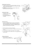
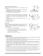
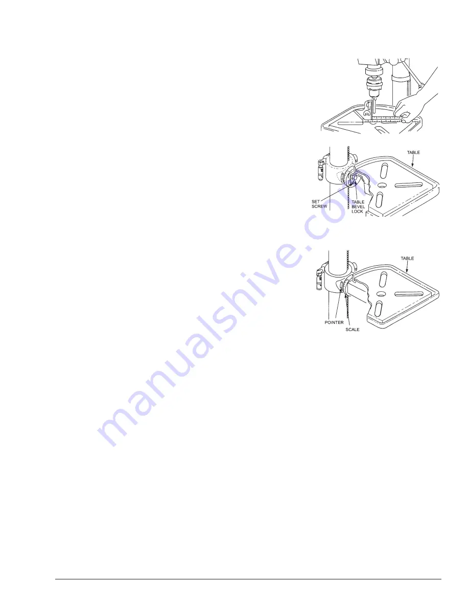
Adjusting the table square to head
Note:
The combination square must be “true”. See “Unpacking” section
for method.
1. Insert a straight ground steel rod or a straight drill bit (not included)
approximately 3” long into chuck and tighten.
2. With table raised to working height and locked on column, place
combination square flat on table beside rod.
3. If an adjustment is necessary, loosen the set screw under bevel lock
with 3mm Hex “L” wrench, then loosen the table bevel lock with the
24mm flat wrench (included). (These adjustments are located under
the table.)
4. Align the table square to the bit by rotating the table until the squre
and bit are in line.
5. Retighten table bevel lock.
6. Retighten set screw.
Bevel scale
Note:
The bevel scale has been included to provide a quick method for
beveling the table to approximate angles. If precise accuracy is
necessary, a square or other precise measuring tool should be used to
position the table.
1. To use the bevel scale, do the following:
a. Loosen set screw and table bevel lock (see step 3 above).
b. Move table so desired angle or bevel scale is straight across
from zero line on table support.
c. Retighten table bevel lock and set screw.
OPERATION
1. Before using this machine, the operator should carefully read over this operation manual to acquaint himself
with the construction, controls and driving system of the machine.
2. All of the Ball Bearing are packed with grease at the factory. They require no further lubrication. Periodically
lubricate the grooves in the spindle and the rack (teeth of the quill).
3. Install drill into chuck far enough to obtain maximum gripping of the chuck jaws. Make sure that the drill is
centered in the chuck. Tighten the drill sufficiently, so that it dose not slip while drilling. Turn the chuck key
clockwise to tighten, counter-clockwise to loosen the drill bit.
4. The drilling depth may be controlled by pointer and depth scale or by the two stop nuts, on the feed stop rod.
5. To position the table, loosen support lock handle, move the table to the desired position and retighten
support lock.
To tilt table, loosen the bevel lock, tilt the table to desired position on the bevel scale and retighten bevel lock.
6. After drilling a hole, release the feed handle to have the spindle sleeve return to its original position.
7. In case of any trouble or abnormal noise arising during operation, stop the motor at once and find out the cause.
8. After operation, remove chips and dirt on the machine and cover all the unpainted surfaces with oil to
prevent them from rusting. Turn off the power supply for safety.
Summary of Contents for 155305
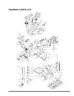
Page 12: ...11 DIAGRAM PARTS LIST ...
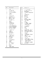
Page 13: ...12 ...


