7
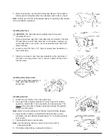
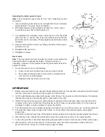
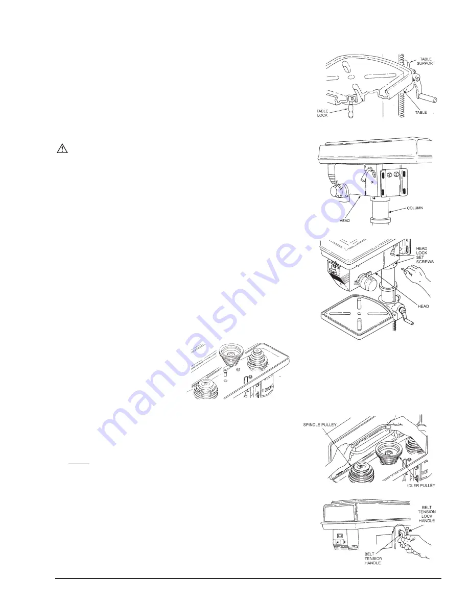
2. Remove protective covering from table and discard. Place table in
table support and tighten table lock (located under table) by hand.
Note:
If table won’t fit into table support easily, try opening table support
with a flat blade screwdriver.
Installing the head
CAUTION:
The head assembly weights about 55 pounds.
Carefully lift head.
1. Remove protective bag from head assembly and discard. Carefully
lift head above column tube and slide it onto column making sure
head slides down over column as far as possible. Align head with
table and base.
2. Locate (2) two 3/8” Dia. x 1/2” long set screws (see illustration) in
loose parts bag.
3. Install a set screw in each hole (as indicated) on the right side of
the head, and using a 5mm hex “L” wrench, tighten the two head
locket screws.
Installing the pulley-center
1. Locate center pulley assembly in
loose parts bag and place in
proper hole.
Installing the belt
1. Locate two (2) V-belts in the loose parts bag.
2. Use speed chart inside belt guard to choose speed for drilling
operation. Install belts in correct position for desired speed. The
longer of the two belts is always positioned between the spindle
pulley and idler pulley.
Note:
Refer to inside belt guard for Recommended Drilling Speeds.
3. Apply tension to belt by turning Belt Tension Handle counter-
clockwise until belt deflects approximately 1/2” by thumb pressure
at its center.
4. Tighten Belt Tension Lock Handles.
Note:
Over-tensioning belt may cause motor not to start or
damage bearings.
5. If belt slips while drilling, re-adjust belt tension.
Summary of Contents for 155305
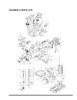
Page 12: ...11 DIAGRAM PARTS LIST ...
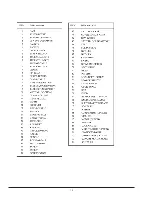
Page 13: ...12 ...


