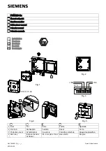
Installing a RTM-8F Module
2. Installation
AFP-100/AFP-100E Instruction PN 51010:C1 02/06/2002
37
3. Municipal Box output: Supervised for open circuit. Output is power-limited and wiring can leave
the building. Yellow Trouble LED, when on, indicates open circuit condition. Check wiring and
make certain Municipal Box is reset according to local codes. Maximum current (short circuit) is 0.6
amps. Maximum Voltage (open circuit) is 30.0 V. Maximum Wire Resistance is 3 ohms.
4. To prevent the yellow Trouble LED from turning on when the Transmitter Output is not used (no
connections), move jumper JP2 to the Local Energy Municipal Box position (bottom two pins) and
install a dummy load across the Transmitter Output terminals as shown below. The dummy load is a
1N4004 diode. The cathode must be connected to the terminal labeled '(–) normal' in Figure 15, and
the anode must be connected to the terminal labeled '(+) normal'. Polarity must be observed or the
Trouble LED will remain on.
Figure 16 Transmitter Output Dummy Load
Caution:
The diode must be removed when using the Transmitter Output to properly supervise the
connections.
Transmitter
Output
1N4004
R
T
M-t
o.c
d
r
!
Technical Manuals Online! - http://www.tech-man.com


