INERTIA-2464
Technical & Programming Manual
Page 7
Copyright (c) 1996,
INERTIA FIRE SYSTEMS
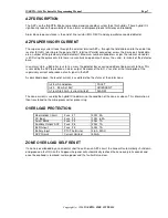
AZF DESCRIPTION
The AZF's on the INERTIA-2464 are monitored and scanned by custom thick film hybrids. These hybrid IC's
significantly reduce the possibility of false alarms and improve product efficiency and reliability.
Alarm Zone loop resistance is the end of line resistor (EOLR 4K7) and any parallel connected detector.
AZF SUPERVISORY CURRENT
The supervisory current flows through the external terminal AZF+, through the field cable and to the end of line
resistor (EOLR), returning to the panel at AZF- terminal. Parallel connected, across the 2-wire pair field cable,
are a number of the previously listed detectors? Maximum number allowable is as per the relevant standards
is 40. During the quiescent state there is essentially an open circuit across the + and - terminals of the detector
base.
In an alarm state, a 560-ohm resistor is across the detector base causing additional loop current to flow. This
is sensed by the AZF to produce an alarm output. Removal of the E.O.L. resistor or the interruption of the
supervisory current will produce a fault signal in the AZF.
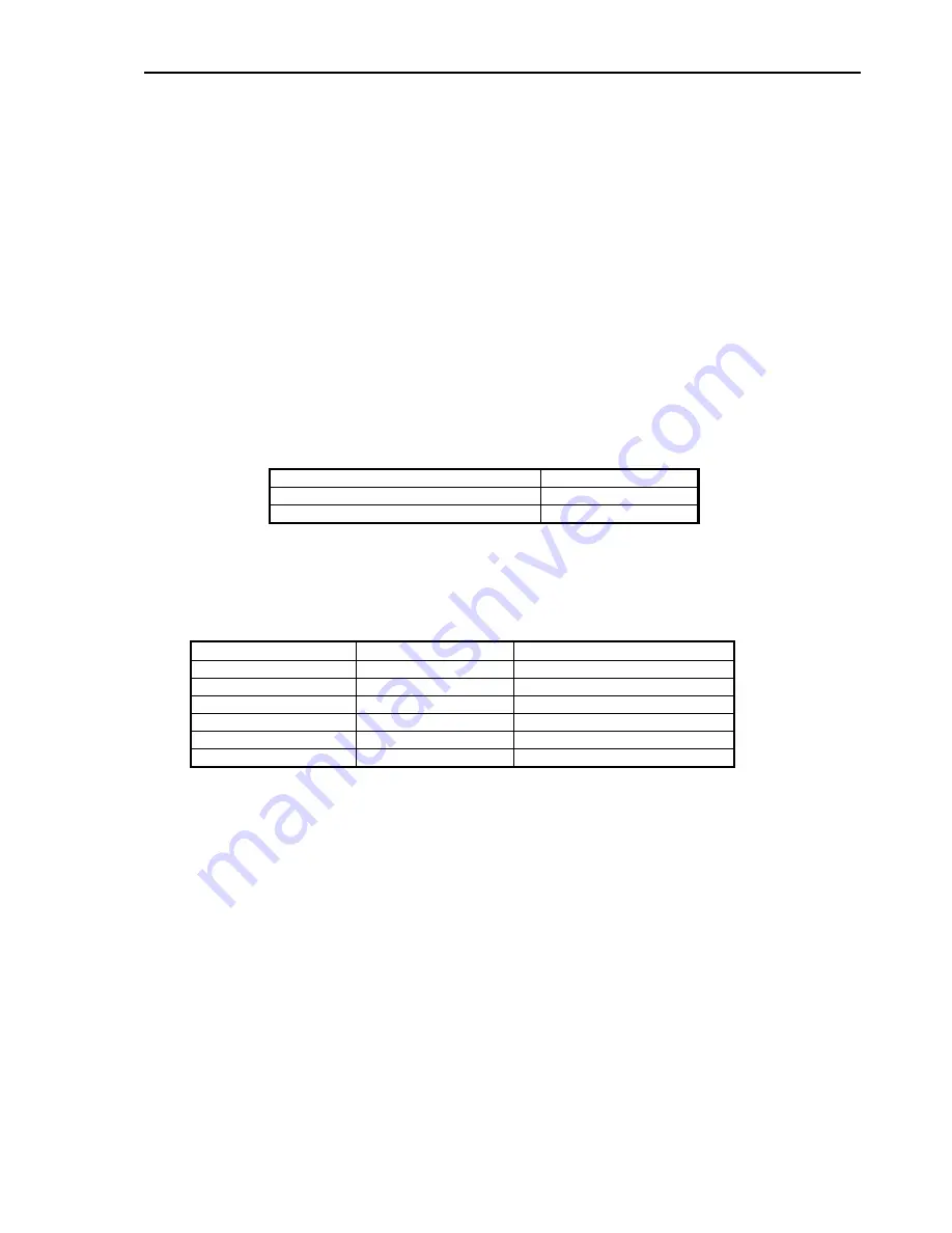
As described above, the level of current is used to define the status of the alarm zone: -
I=3.5 mA and below
FAULT
I=4.0 - 5.0mA at 24V
QUIESCENT
I=16 mA to 40 mA (current limited)
ALARM
The zone current is used by the hybrid IC to determine the condition of the zone as above. This information is
then transferred to the microprocessor for processing.
OVERLOAD PROTECTION
Door Holder Circuit
Fuse F1
3AG 3A
AC Input
Fuse F2
1AG 6.3A
Aux & Mimic
Fuse F3
3AG 1A
Ancillary Output ACF
Fuse F4
2AG 1A
Bell Output
Fuse F5
3AG 1A
Battery Input
PTC Thermistor
3.6A MAX
AZF Circuits
Current Limited
40mA
ZONE OVERLOAD SELF RESET
If a zone is overloaded by an accidental short to earth on an AZF circuit, the zone will automatically shut down
and produce a fault. Once this happens the panel will automatically recheck the zone every 60 seconds and
once the overload is removed, restore power and the fault will also clear.
Summary of Contents for INERTIA-2464/64
Page 58: ......
Page 59: ...INERTIA 2464 Technical Programming Manual Page 1 Copyright c 1996 INERTIA FIRE SYSTEMS...
Page 60: ...Page 2 INERTIA 2464 Technical Programming Manual Copyright c 1996 INERTIA FIRE SYSTEMS...
Page 61: ...INERTIA 2464 Technical Programming Manual Page 3 Copyright c 1996 INERTIA FIRE SYSTEMS...


