background image

Page 10 


INERTIA-2464

 Technical & Programming Manual 

Copyright (c) 1996, 

INERTIA FIRE SYSTEMS


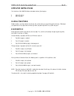
IFS800  - JP3  DEFAULT (MEMORY RESET) 


Holding a short across these pins for 5 seconds during start-up causes the panel to reset to standard 

factory defaults. The panel will give 4 beeps after reset, to acknowledge default on startup.  


IFS800  - JP4   PROGRAM DISABLE 


When fitted, jumper between these pins to inhibit program changes.  


IFS800  - JP5   CPU RESET 


With panel operating, a momentary short across these pins will cause a CPU restart. 


IFS801L - JP3   DOOR HOLDER BYPASS 


If zoned door holder outputs are required and is to be done external to the main termination board, 

then the main door holder release needs to be disabled. Fitting a link across JP3 on IFS801 PCB does 

this.  


Note: Door holder output is only enabled if optional door holder transformer is fitted. 


IFS801L - JP4   EXTERNAL POWER SUPPLY ENABLE/DISABLE 


Jumper link remains fitted when the internal supply only is being used. 


Jumper link is to be cut when an external power supply is being used.  


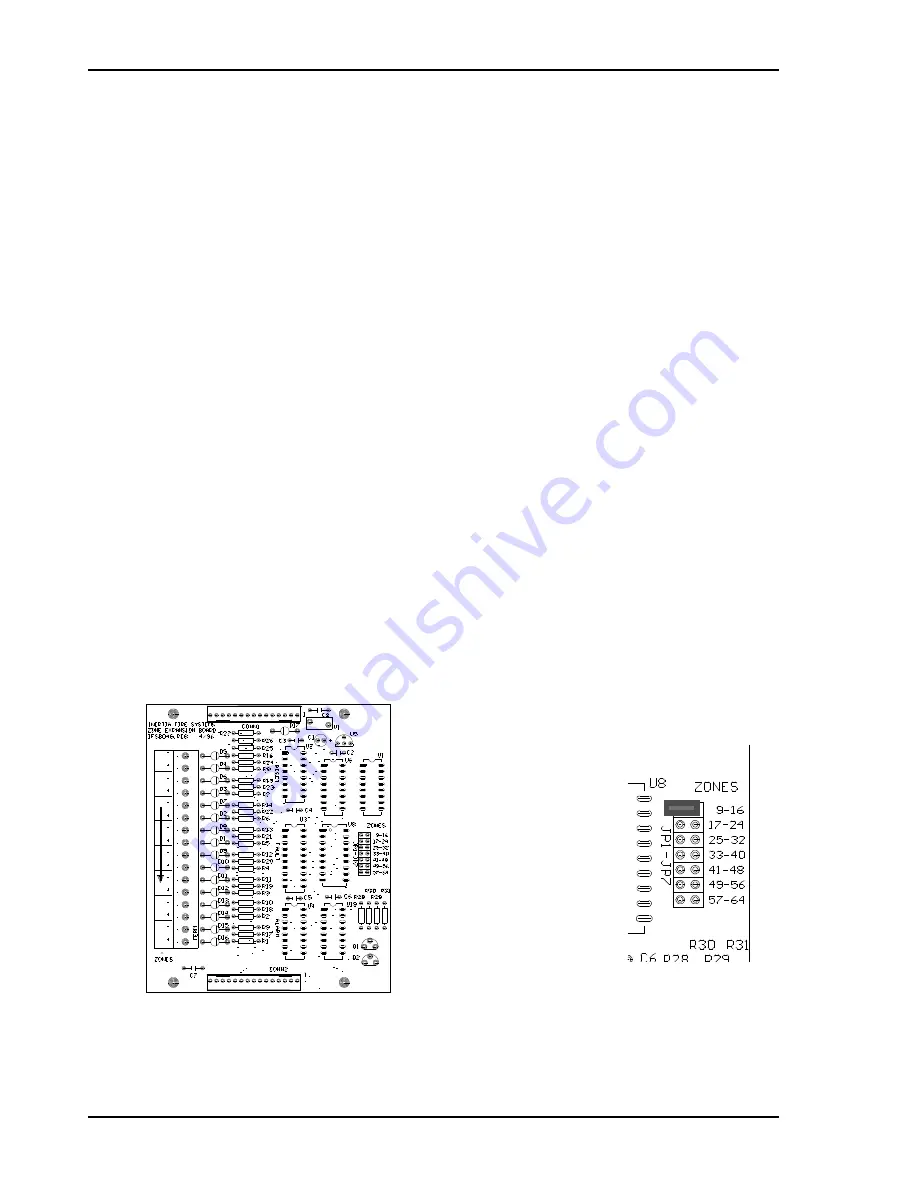
IFS804G - JP1-7 ZONE BOARD ADDRESSING  


Jumper JP1 to JP7 on zone expansion board IFS-804 selects the addressing for the zones. 


Place jumper in link position for the appropriate 8 zones to which the expansion board applies. 


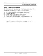
Summary of Contents for INERTIA-2464/64

Page 1: ...tralian SSL Approval No 215 Australian SSL Quality Accredited Hong Kong Fire Services Dept Approved PROC Standard GB4717 93 C Tick Approval No N1336 Serial No Date of Manufacture 7 COLUMBIA COURT NORW...

Page 2: ...LKJ Hochiki Smoke Ionisation SIJ ASN SIH AM Hochiki Smoke Photo Optical SLR AS SLK A System Sensor Thermal Type A 5451AUS System Sensor Thermal Type B 4451AUS System Sensor Smoke Photo Optical 2151AUS...

Page 3: ...SUPPLY if fitted 9 INTERNAL 5VDC POWER SUPPLY TP4 9 POWER SUPPLY COMPARATOR REFERENCE VOLTAGE TP1 9 PLACING INTO OPERATION 11 INITIAL CHECKLIST 11 POWER UP CHECKLIST 11 FUNCTIONAL TESTING 12 FAULT RE...

Page 4: ...D MAPPING 41 OR MAPPING 41 FAULT MAPPING 41 FAULT ISOLATE MAPPING 41 ISOLATE MAPPING 42 APPENDIX F 43 GLOSSARY OF TERMS 43 APPENDIX G 44 SUMMARY OF TERMINATIONS AND CAUTIONS 44 MCP LOOP 44 DETECTION Z...

Page 5: ...INERTIA 2464 Technical Programming Manual Page 1 Copyright c 1996 INERTIA FIRE SYSTEMS Section One TECHNICAL MANUAL...

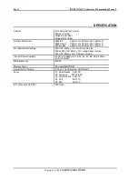
Page 6: ...x 280mm H x 390mm W x 160mm D AC Operational Voltage 240 VAC 50Hz 10 Australian Version 200 or 220 VAC 50Hz 10 Hong Kong Version 220 VAC 50Hz 10 Chinese Version Internal Power Supplies 24 VDC 3 0AMP i...

Page 7: ...ard PCB 804G 3 Zone Indicator board PCB 802 40 1 Main Control board PCB 800 1 Main Termination board PCB 801L 4 Zone Expansion board PCB 804G 4 Zone Indicator board PCB 802 48 1 Main Control board PCB...

Page 8: ...24VDC 1A each PCB 813 16 2 Open collector output board 8 outputs 24VDC 1A each PCB 813 24 3 Open collector output board 8 outputs 24VDC 1A each PCB 813 32 4 Open collector output board 8 outputs 24VDC...

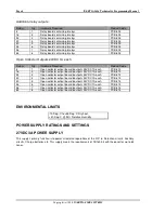
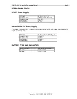
Page 9: ...AMPS Output Ripple 50 mV Internal 5VDC 2A Power Supply This supply s primary function is to power all internal operations of the FIP ie Microprocessor liquid crystal display LED s keypad etc AC Input...

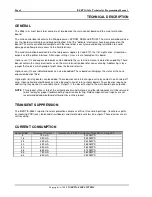
Page 10: ...es the board refers to Up to seven 7 zone indicator boards can also be added These boards will displays the status of the zone expansion boards fitted Up to eight 8 relay boards can be added These boa...

Page 11: ...etector base causing additional loop current to flow This is sensed by the AZF to produce an alarm output Removal of the E O L resistor or the interruption of the supervisory current will produce a fa...

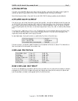
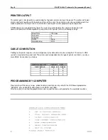
Page 12: ...erial printer ASCII printer with the following settings Baud Rate 1200 bps Data Bits 8 Stop Bits 1 Parity None Handshaking DTR CABLE CONNECTION Cabling to the printer requires a 4 core telephone style...

Page 13: ...e voltage across AUX 0V AUX 24V on PCB801 and adjust the voltage on the external power supply untill the AUX voltage is 27 6V 1 Current limiting is preset adjustment is not required INTERNAL 5VDC POWE...

Page 14: ...P3 DOOR HOLDER BYPASS If zoned door holder outputs are required and is to be done external to the main termination board then the main door holder release needs to be disabled Fitting a link across JP...

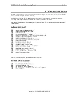
Page 15: ...t Colour and Condition Good Cabinet Keyed 003 All Circuit Boards Firmly Fastened Manual Call Point Fitted Functional Australian version only Viewing Window Clear and Firmly Secured Cable Entries Adequ...

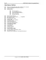
Page 16: ...n Internal Sounder Operating MCP Loop Wired To Zone Number ______ if applicable Door Switch Functional Test Auxiliary Power Output Test Bell Output Test Door Holder Output optional Test Ancillary Outp...

Page 17: ...CORRECTION DATE TESTS SATISFACTORILY COMPLETED TESTED BY _______________________________ SIGNATURE _______________________________ DATE OF TEST ____________________________ If all faults have been rec...

Page 18: ...ndicator panel door or press any buttons until fire officers arrives Determine location of the fire Visually inspect area at a safe distance for actual fire or false alarm Notify fire monitoring stati...

Page 19: ...follows If the panel door is opened and there are NO alarms present 1 The BELL output is isolated 2 The ACF output is isolated 3 The DOOR HOLDER output is held energised If the panel door is opened a...

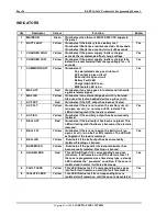
Page 20: ...activated 1 ACF FLT Yellow Illuminates if there is no load on the ancillary circuit an open circuit ie no relay or EOL resistor The LED will extinguish if the load is restored Yes 1 ACF ISO Yellow Ill...

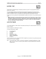
Page 21: ...short circuited for a period of 30 seconds the Battery Fault LED will illuminate and provide a common fault This automatic battery monitoring functions in quiescent mode and is therefore disabled if t...

Page 22: ...he appropriate alarm LED for 4 seconds the bells will also ring for a 3 second period unless previously isolated The zone and detector will then be automatically reset If the optional printer is conne...

Page 23: ...essing silence will have no effect on the display If the buzzer or bell isolate LEDS are illuminated due to a silence operation once the zone s in alarm is reset the isolate LEDS will be automatically...

Page 24: ...atching isolating the ACF will not effect the existing ancillary output If the ACF is isolated prior to the alarm it will prevent the ancillary output from tripping Note If the ACF output is programme...

Page 25: ...ammed similar to a real alarm The zone may be isolated prior to alarm test if desired this will prevent any outputs from operating The character in the keystrokes above requires any one the following...

Page 26: ...t The zone may be isolated prior to fault test if desired This will prevent any outputs from operating The character in the keystroke requires any one of the following entries 1 2 3 4 63 64 or ALL If...

Page 27: ...s 1 Press the ISOLATE button The buzzer will give 2 short beeps to indicate that isolate mode has been entered 2 The LCD display will read ALARM ISOL MODE ENTER ZONE No 3 Enter the zone number 4 Press...

Page 28: ...Alternatively the ALL button can be used to simultaneously reset all zones To perform a reset on a particular zone or on all zones 1 Press the RESET button 2 The buzzer will give 2 short beeps to ind...

Page 29: ...ITTED QTY Description Code 1 MAIN CONTROL BOARD PCB 800 1 MAIN TERMINATION BOARD PCB 801L OPTION ZONE EXPANSION BOARD PCB 802 OPTION ZONE INDICATOR BOARD PCB 804G OPTION ADD ON RELAY BOARD PCB 803 OPT...

Page 30: ...Page 26 INERTIA 2464 Technical Programming Manual Copyright c 1996 INERTIA FIRE SYSTEMS Section Two PROGRAMMING MANUAL...

Page 31: ...UT DELAY 1 Standard Latching 2 seconds 2 Standard Latching 2 seconds with AVF 3 Non Latching 2 seconds 4 Non Latching 20 seconds 5 Time Delay 10 seconds 6 Time Delay 20 seconds 7 Time Delay 30 seconds...

Page 32: ...ones in Alarm MAP OR Up To 5 Zones in Alarm FAULT MAP Up To 5 Zones in Fault MAP ISOLATE Up to 5 Zones in Isolate MAP ISO FAULT Up to 5 Zones in Isolate Fault DEFAULTS ACF OUTPUT NON LATCHING NORMALLY...

Page 33: ...eys are used in programming mode All other keys will give an error beep and are ignored You must exit programming mode if any other panel functions are to be performed Note Refer to appendices for det...

Page 34: ...AULT 00 00 00 00 00 DOOR SWITCH RESET GLOBAL ACF AVF RELAY TIME NON LATCHING ND DISABLED MAP RELAY XX DD MM YY LATCHING ND 2 MINUTES FROM ZONE XX HH MM NON LATCHING NE 3 MINUTES LATCHING NE 4 MINUTES...

Page 35: ...o the time ZONE PROGRAMMING SELECT ZONE SELECT ZONE ALL Use the NEXT PREVIOUS keys to scroll through ALL 1 2 3 Up to the maximum number of zones fitted and then wrap around Once the desired zone numbe...

Page 36: ...option has been highlighted pressing the SELECT button will select Pressing EXIT at this stage will return to Zone Selected Note The option previously set is displayed in brackets and is the first to...

Page 37: ...and is the first to be displayed Previously set options will not be displayed if ALL is selected RELAY MAPPING RELAY 1 MAP 00 00 00 00 00 Relay mapping can only be selected if the relay is set as a MA...

Page 38: ...ING ND NON LATCH NE LATCHING NE Note The option previously set is displayed in brackets and is the first to be displayed ND Normally De energised ie Output is not energised until an alarm occurs NE No...

Page 39: ...E 09 Then relay 1 would be set as MAP OR with its mapping as 09 00 00 00 00 relay 2 would be set as MAP OR with it s mapping set as 10 00 00 00 00 and so on all the way up to relay 64 Note In example...

Page 40: ...e and alarm functions are initiated immediately unless zone is set as AVF refer Appendix C The alarm zone will remain in alarm until manually reset A reset is performed by interrupting the power to th...

Page 41: ...within this 10 second period will return the zone back to its normal state immediately and extinguish the alarm LED If an alarm is received the detector is reset again and TIMER 2 is also reset This m...

Page 42: ...2 Indicate Bell 3 Indicate Bell General Alarm 4 Indicate Bell General Alarm Ancillary 5 Indicate Bell General Alarm Ancillary Brigade Relay 1 6 Indicate Bell General Alarm Ancillary Brigade Relay 2 7...

Page 43: ...reset by shutting down power to their detectors for 12 seconds the power is then restored and the zones are re enabled The alarm verification zones are now in alert mode Any AVF zone going into alarm...

Page 44: ...P ACF NON LATCHING ND LATCHING ND NON LATCHING NE LATCHING NE The ancillary trip can be programmed as latching or non latching depending on the application It call also be programmed as normally energ...

Page 45: ...NG AND MAPPING which allows the relay output to be programmed so if a programmed combination of up to 5 zones all go into alarm the relay will operate AND MAPPING is useful for applications which have...

Page 46: ...isolate If the relay map options are set as 01 02 03 00 00 then zones 1 or 2 or 3 going into fault or are manually put in isolate will cause the relay to operate ISOLATE MAPPING ISOLATE MAPPING works...

Page 47: ...ntilation and Air Conditioning Fire Precautions in Buildings with Air handling Systems AZF Alarm Zone Facility zone MAF Master Alarm Facility ACF Ancillary Control Facility AVF Alarm Verification Faci...

Page 48: ...ttempt to switch 240VAC with these relay contacts Note Relay Contacts Shown At Terminals NC C NO Are For The Relay In a De Energised State BELL OUTPUTS This output is fused at 1 Amp and can drive up t...

Page 49: ...OT connect 240VAC to these terminals BATTERY The 24V batteries are connected at these terminals Reverse polarity can cause serious and permanent damage to the equipment DOOR HOLDER AC INPUT Terminate...

Page 50: ...996 INERTIA FIRE SYSTEMS APPENDIX H 2464 PROGRAMMED OPTIONS Global System Parameters Date Latch ND Non Latch ND Latch NE Non Latch NE ACF Output Disabled 2 min 3 min 4 min 5 min Alarm Verification AVF...

Page 51: ...FIRE SYSTEMS ZONE TYPE PROGRAMMING Date 1 2 3 4 5 6 7 8 9 10 AZF No STD STD N L N L T D T D T D T D T D T D 2S AVF 2S 20S 10S 20S 30S 40S 50S 60S 1 2 3 4 5 6 7 8 9 10 11 12 13 14 15 16 17 18 19 20 21...

Page 52: ...INERTIA FIRE SYSTEMS 1 2 3 4 5 6 7 8 9 10 AZF No STD STD N L N L T D T D T D T D T D T D 2S AVF 2S 20S 10S 20S 30S 40S 50S 60S 33 34 35 36 37 38 39 40 41 42 43 44 45 46 47 48 49 50 51 52 53 54 55 56...

Page 53: ...c 1996 INERTIA FIRE SYSTEMS ZONE OUTPUT PROGRAMMING Date AZF No INDICATE I BELL IB GENERAL IBG ACF IBGA BR1 IBGA BR2 IBGA BR1 BR2 1 2 3 4 5 6 7 8 9 10 11 12 13 14 15 16 17 18 19 20 21 22 23 24 25 26...

Page 54: ...Copyright c 1996 INERTIA FIRE SYSTEMS AZF No INDICATE I BELL IB GENERAL IBG ACF IBGA BR1 IBGA BR2 IBGA BR1 BR2 33 34 35 36 37 38 39 40 41 42 43 44 45 46 47 48 49 50 51 52 53 54 55 56 57 58 59 60 61 6...

Page 55: ...INERTIA FIRE SYSTEMS MAPPING RELAY OUTPUT MAPPING Date RLY ISO ACF BR1 BR2 FLT MAINS FAIL GEN BELL D H AND OR FLT ISO ISO FLT DO OR RE SET 1 2 3 4 5 6 7 8 9 10 11 12 13 14 15 16 17 18 19 20 21 22 23 2...

Page 56: ...ming Manual Copyright c 1996 INERTIA FIRE SYSTEMS MAPPING RLY ISO ACF BR1 BR2 FLT MAINS FAIL GEN BELL D H AND OR FLT ISO ISO FLT DO OR RE SET 33 34 35 36 37 38 39 40 41 42 43 44 45 46 47 48 49 50 51 5...

Page 57: ...Manual Page 53 Copyright c 1996 INERTIA FIRE SYSTEMS APPENDIX I TECHNICAL DRAWINGS L2400_1 Presentation Drawing Rev A L2400_3 System ConFiguration Rev A E2400_1 Typical Output Connection Rev A 2464PS...

Page 58: ......

Page 59: ...INERTIA 2464 Technical Programming Manual Page 1 Copyright c 1996 INERTIA FIRE SYSTEMS...

Page 60: ...Page 2 INERTIA 2464 Technical Programming Manual Copyright c 1996 INERTIA FIRE SYSTEMS...

Page 61: ...INERTIA 2464 Technical Programming Manual Page 3 Copyright c 1996 INERTIA FIRE SYSTEMS...

Page 62: ...ny way is prohibited Drawing File No C O 61 2 9894 1444 61 2 9899 4156 Q JOBS PROTEL GENERAL 2400 24 9A_1 SCH Of MAINS ISOLATION SWITCH 240V 30V 300VA TRANSFORMER 400V 25A BRIDGE BATTERY 24V OUTPUT TO...

Reviews: