Page 12
INERTIA-2464
Technical & Programming Manual
Copyright (c) 1996,
INERTIA FIRE SYSTEMS
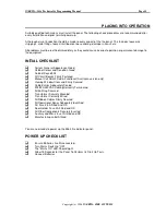
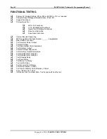
FUNCTIONAL TESTING
Primary AC Supply Voltage: 200 or 220 or 10% as required
Charger Output Voltage without Batteries: 27.6V DC
Keypad Functional
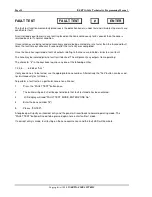
Perform Auto Test
LED's All Functional
L.C.D Backlighting Functional
Liquid Crystal Display Functional
Zone Fault Detection
Zone Alarm Detection
Internal Sounder Operating
MCP Loop Wired To Zone Number ______ (if applicable)
Door Switch Functional
Test Auxiliary Power Output
Test Bell Output
Test Door Holder Output (optional)
Test Ancillary Output
Test Bell Output Supervision
Test Ancillary Output Supervision
Test Brigade Alarm Relay #1
Test Brigade Alarm Relay #2
Test Standby Relay
Test Fault Relay
Test Mains Fail Relay
Test Isolate Relay
Test General Alarm Relays
Test Relay Boards (if fitted)
Test Open Collector Output Boards (if fitted)
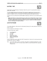
Press "Battery Test" Once
If Batteries Are Flat, Allow 24hrs To Charge And Then Re-test.
Summary of Contents for INERTIA-2464/64
Page 58: ......
Page 59: ...INERTIA 2464 Technical Programming Manual Page 1 Copyright c 1996 INERTIA FIRE SYSTEMS...
Page 60: ...Page 2 INERTIA 2464 Technical Programming Manual Copyright c 1996 INERTIA FIRE SYSTEMS...
Page 61: ...INERTIA 2464 Technical Programming Manual Page 3 Copyright c 1996 INERTIA FIRE SYSTEMS...


