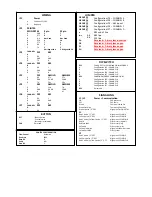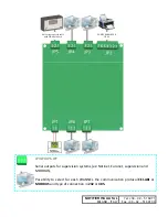
WIRING
JP1
Power
1
Positive
+
12/24V
2
Negative
JP2
PRINTER
MOD
‐
PRT
‐
M
9
pin
25
pin
1
GND
5
7
2
RTS
8
5
3
N.U.
Not
Used
Not
Used
4
DSR
4
20
5
CTS
7
4
6
RX
3
2
7
TX
2
3
6
bridge
with
4
6
bridge
with
20
JP3
CHANNEL
A
232
485
1
RX
L
2
GND
GND
3
TX
H
JP4
CHANNEL
B
232
485
1
RX
L
2
GND
GND
3
TX
H
JP5
232
AMOLD
AMNEW
1
RX
4
Tx
2
Tx
2
GND
6
GND
5
GND
3
TX
5
Rx
3
Rx
JP5
485
AMOLD
AMNEW
1
L
11
H
7
H
2
GND
6
GND
5
GND
3
H
7
L
6
L
JP6
CHANNEL
C
232
485
1
RX
L
2
GND
GND
3
TX
H
JP7
CHANNEL
D
232
485
1
RX
L
DIP
SWITCH
DS1
Setting OFF
for CEI
‐
ABI
and
ON
for
MODBUS
1
Configuration
JP3
–
CHANNEL
A
2
Configuration
JP4
–
CHANNEL
B
3
Configuration
JP6
–
CHANNEL
C
4
Configuration
JP7
–
CHANNEL
D
DS2
ENABLING
MODBUS
COMMANDS
(ON)
1
Configuration
JP3
–
CHANNEL
A
2
Configuration
JP4
–
CHANNEL
B
3
Configuration
JP6
–
CHANNEL
C
4
Configuration
JP7
–
CHANNEL
D
DS3
Rerserved
JUMPER
GROUP P3
Configuration
JP3
–
CHANNEL
A
GROUP P4
Configuration
JP4
–
CHANNEL
B
GROUP P5
Configuration
JP5
–
AM
Inpunt
GROUP P6
Configuration
JP6
–
CHANNEL
C
GROUP P7
Configuration
JP7
–
CHANNEL
D
a
485
end
of
line
b
‐
c
1
‐
2
485 line
2
‐
3
232 line
PA
Reserved
– Alwasy
leave
inserted
PB
Reserved
– Alwasy
leave
open
PC
Reserved
– Alwasy
leave
open
PU
Reserved
– Alwasy
leave
open
SIGNALLING
L1
/L2
Power +
Communication
ON
24V
presence
OFF
24V
fault
Green
Communication OK
Green
fast
blink
Tampering
Com.
AM
Green 1
pulse /
2”
OFF
Alignment
MOD
‐
PRT
‐
M
L1
Red
1
pulse
/
2”
OFF
Alignment
CEI
‐
ABI
A
Yello
1
pulse
/
2”
OFF
Alignment
CEI
‐
ABI
B
Red
1
pulse
/
Yellow
1
pulse
/
2”
OFF
Alignment
CEI
‐
ABI
A+B
Red fix
history
log
wait
Red
fast
blink
history
log
Yellow
fix
system
wait
Yellow
slow
blink
Alignment
chamber
value
Yellow
fast
blink
system
L2
Red
1
pulse
/
2”
OFF
Alignment
CEI
‐
ABI
C
Yellow
1
pulse /
2”
OFF
Alignment
CEI
‐
ABI
D
Red
1
pulse
/
Yellow
1 pulse/
2”
OFF
Alignment
CEI
‐
ABI
C+D
BUTTON
RST
‐
Events
Delete
‐
selection
‐
System
selection
SW1
Rererved
PRINTER
CONFIGURATION
Flow
Control
Hardware
Buad
rate
9600
Data
Bit
8
Parity
NO
Stop
Bit
1
Summary of Contents for MOD-PRT-M
Page 3: ......


