10
Simplex 4010 NION Installation/Operation Manual Version 2 Document 51998 Rev. A1 03/26/03
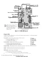
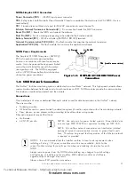
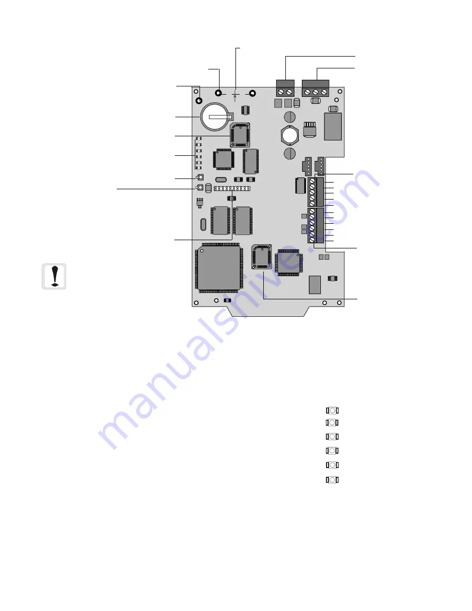
Figure 1-1: NION-NPB Layout
Service LED
- Indicates binding status of node on Echelon network.
•
Slow blink indicates NION not bound.
•
Off indicates NION bound.
•
On indicates nonrecoverable error.
Network Status
- Indicates status of Echelon network interface.
•
Slow blink indicates network operation normal.
•
Off indicates network interface not functioning.
•
Fast blink indicates a network communication error.
Network Packet
- Blinks briefly each time a data packet is received or transmitted on the Echelon network.
Serial 2
- Application specific indicator of serial port activity (port 2).
Serial 1
- Application specific indicator of serial port activity (port 1).
NION Status
- Indicates status of the NION.
•
Rapid blinking indicates proper NION operation.
•
On or Off indicates critical error and that the NION is not functioning.
Diagnostic LEDs
The NION contains six LEDs which are used as aids in diagnosing proper operation. The following paragraph
details the function of each LED.
Service
Service
Service
Service
Service
Network Status
Network Status
Network Status
Network Status
Network Status
Network P
Network P
Network P
Network P
Network Packet
acket
acket
acket
acket
Serial 2
Serial 2
Serial 2
Serial 2
Serial 2
Serial 1
Serial 1
Serial 1
Serial 1
Serial 1
NION Status
NION Status
NION Status
NION Status
NION Status
3V Lithium
3V Lithium
3V Lithium
3V Lithium
3V Lithium
Battery
Battery
Battery
Battery
Battery
J1 Header for Echelon
J1 Header for Echelon
J1 Header for Echelon
J1 Header for Echelon
J1 Header for Echelon
Network T
Network T
Network T
Network T
Network Transceiver
ransceiver
ransceiver
ransceiver
ransceiver
Application PLCC
Application PLCC
Application PLCC
Application PLCC
Application PLCC
SW2 Network
SW2 Network
SW2 Network
SW2 Network
SW2 Network
Binding Button
Binding Button
Binding Button
Binding Button
Binding Button
SW1 Reset
SW1 Reset
SW1 Reset
SW1 Reset
SW1 Reset
Button
Button
Button
Button
Button
Network Communication PLCC
Network Communication PLCC
Network Communication PLCC
Network Communication PLCC
Network Communication PLCC
SMX T
SMX T
SMX T
SMX T
SMX Transceiver
ransceiver
ransceiver
ransceiver
ransceiver
Standoff Mounting
Standoff Mounting
Standoff Mounting
Standoff Mounting
Standoff Mounting
Holes
Holes
Holes
Holes
Holes
Chassis
Chassis
Chassis
Chassis
Chassis
Ground
Ground
Ground
Ground
Ground
Diagnostic LEDS
Diagnostic LEDS
Diagnostic LEDS
Diagnostic LEDS
Diagnostic LEDS
R72 Cut T
R72 Cut T
R72 Cut T
R72 Cut T
R72 Cut To Disable Ground
o Disable Ground
o Disable Ground
o Disable Ground
o Disable Ground
Fault Detection
Fault Detection
Fault Detection
Fault Detection
Fault Detection
GND +24VDC
PPPPPower Input (TB5)
ower Input (TB5)
ower Input (TB5)
ower Input (TB5)
ower Input (TB5)
TB6-Relay Output
TB6-Relay Output
TB6-Relay Output
TB6-Relay Output
TB6-Relay Output
U24
U24
U24
U24
U24
BT1
BT1
BT1
BT1
BT1
U6
U6
U6
U6
U6
TB7 - RS-485 Interface
TB7 - RS-485 Interface
TB7 - RS-485 Interface
TB7 - RS-485 Interface
TB7 - RS-485 Interface
NO
NO
NO
NO
NOTE
TE
TE
TE
TE: The NION-
: The NION-
: The NION-
: The NION-
: The NION-
Simplex 4010 does not
Simplex 4010 does not
Simplex 4010 does not
Simplex 4010 does not
Simplex 4010 does not
use this connection.
use this connection.
use this connection.
use this connection.
use this connection.
TB1- 5-
TB1- 5-
TB1- 5-
TB1- 5-
TB1- 5-W
W
W
W
Wire Serial
ire Serial
ire Serial
ire Serial
ire Serial
Interface A
Interface A
Interface A
Interface A
Interface A
RX
GND
CTS
RTS
TX
+5VDC
GND
RX+
RX-
TX+
TX-
NOTE: There is a paper insulator
between the battery and the
battery clip installed at the factory
to keep the battery charged.
Remove the insulator before
applying power.
Technical Manuals Online! - http://www.tech-man.com
firealarmresources.com


