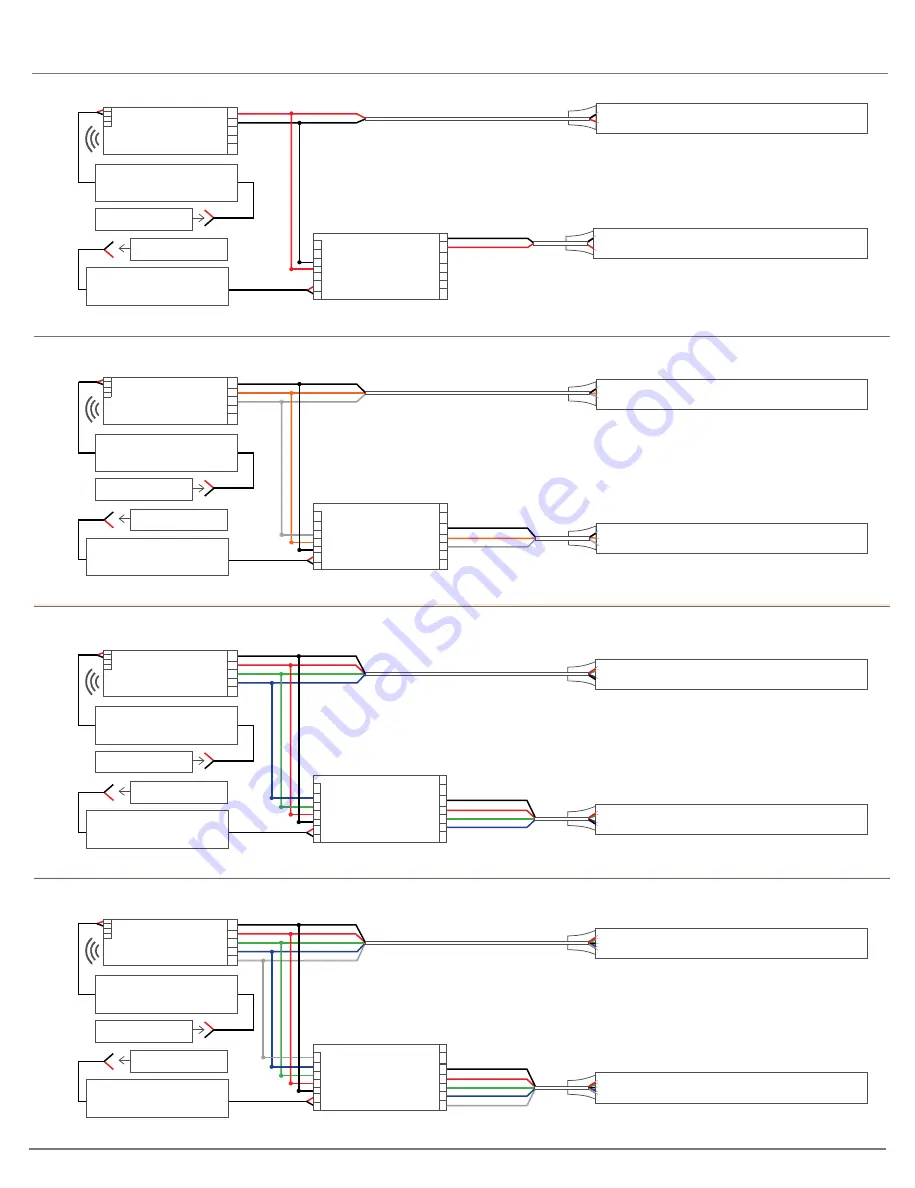
WIRING DIAGRAM
S3i Series
Ribbon: 14 - 20 Gauge Wire | Neon: 12 - 18 Gauge Wire
S3i Wireless Receiver - RGBW
Run #1
Run #2
RGBW Ribbon or Neon
RGBW Ribbon or Neon
NF-A-UNV
INPUT
W- B- G
- R- + v+ v-
OUTPUT
W- B- G
- R- V+
V+ V-
Red Wire = R-
|
Green Wire = G-
|
Blue Wire = B-
|
White Wire (Gray) = W-
|
Black Wire = V+
S3i Wireless Receiver - RGB
NF-S3i-WR-1009
NF-PS-HLG100W-24V-HW
NF-PS-HLG100W-24V-HW
Run #1
Run #2
120V AC (Line)
120V AC (Line)
INPUT
OUTPUT
RGB Ribbon or Neon
RGB Ribbon or Neon
-
+ -
+
NF-A-UNV
INPUT
W- B- G
- R- + v+ v-
OUTPUT
W- B- G
- R- V+
W- B- G
- R- V+
NF-S3i-WR-1009
NF-PS-HLG100W-24V-HW
NF-PS-HLG100W-24V-HW
120V AC (Line)
120V AC (Line)
INPUT
OUTPUT
-
+ -
+
W- B- G
- R- V+
NF-S3i-WR-1009
NF-PS-HLG100W-24V-HW
NF-PS-HLG100W-24V-HW
120V AC (Line)
120V AC (Line)
INPUT
OUTPUT
-
+ -
+
W- B- G
- R- V+
V+ V-
Red Wire = R-
|
Green Wire = G-
|
Blue Wire = B-
|
Black Wire = V+
S3i Wireless Receiver - Adjustable
Run #1
Run #2
Adjustable Ribbon or Neon
Adjustable Ribbon or Neon
NF-A-UNV
INPUT
W- B- G
- R- + v+ v-
OUTPUT
W- B- G
- R- V+
V+ V-
Black Wire = V+
|
Yellow Wire (Orange) = V-
|
White Wire (Gray) = V-
NF-S3i-WR-1009
NF-PS-HLG100W-24V-HW
NF-PS-HLG100W-24V-HW
120V AC (Line)
120V AC (Line)
INPUT
OUTPUT
-
+ -
+
W- B- G
- R- V+
S3i Wireless Receiver - Static
Run #1
Run #2
Static Ribbon or Neon
Static Ribbon or Neon
NF-A-UNV
INPUT
B- G- R- + V- V+ V-
OUTPUT
W- B- G
- R- V+
V+ V-
Black Wire = V-
|
Red Wire = V+
Note: Gray Wire = White Wire
Note: Gray Wire = White Wire


