background image

33

HOW TO AssEMBLE THE COnTrOL PAnEL

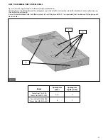
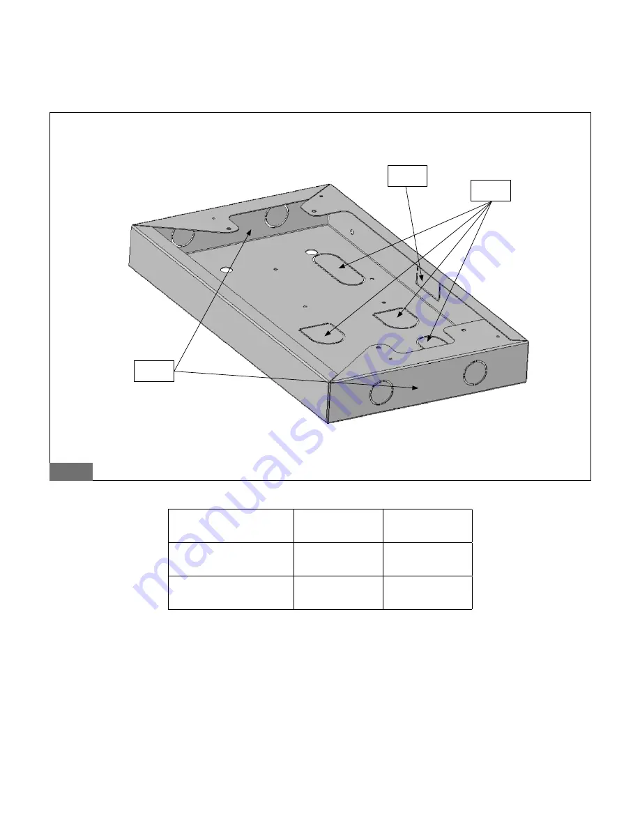
Fig. 21 shows the support used to fix the control panel to the boiler.
The openings in the bottom (A) and the rectangular one in the side (C) (in case when used with a bracket) can be used for passing
the capillary tubes through.
In case of need, additional side slots (B) are present to host fittings model PG 21 (not provided), that can be used for the passage of
electric cables.

fig. 21

Model

Openings for

cables

Openings for

capillary tubes

Taurus Dual 70÷1300

Taurus Dual HR 70÷1300

A - B

A

Taurus Dual 1400÷3500

Taurus Dual HR 1400÷3500

B

C

A

C

B

Summary of Contents for Taurus Dual 100

Page 1: ...PRESSURISED STEEL BOILER INSTALLATION USE AND MAINTENANCE IST 04 C 235 03 TAURUS DUAL TAURUS DUAL HR EN...

Page 2: ...nform the User that The boilers must be installed by a qualified installer strictly adhering to the regulations in force The installer is obliged by Law to issue a Declaration of Conformity with the r...

Page 3: ...aging into the environment during installation All materials are recyclable and must be placed at the appropriate differentiated collection points In the case of faults and or defective functioning of...

Page 4: ...ssure 6 bar 14 3 2 3 2 Thermal hot water system with closed expansion vessel Furnace output 300 000 kcal h pressure 6 bar 14 3 2 4 Air intake flue gas systems 15 3 3 Electrical connection 16 3 3 1 Wir...

Page 5: ...ates that the burner is receiving electrical power request for heat 9 Thermometer The function of the thermometer is to indicate the flow water temperature 10 Overheating thermostat with manual reset...

Page 6: ...red GREEN n a n a OFF YELLOW Request for DHW active 1 GREEN YELLOW OFF OFF YELLOW Request for CH active GREEN OFF YELLOW OFF YELLOW Shutdown due to safety thermostat triggering GREEN n a n a RED OFF T...

Page 7: ...utdown due to overheating If the red overheating light 10 lights up indicating that the manual reset safety thermostat has activated due to a malfunction contact qualified personnel who satisfy the re...

Page 8: ...kW 2000 HR 2000 heat output 2000 kW 2400 HR 2400 heat output 2400 kW 3000 HR 3000 heat output 3000 kW 3500 HR 3500 heat output 3500 kW The boilers are fitted with a right or left hinged door The oute...

Page 9: ...850 1864 1500 523 980 437 200 250 180 250 65 65 1 1 1 2 1 2 400 HR 400 1190 1015 500 1095 500 50 940 890 1872 1502 600 850 422 230 280 225 250 80 80 1 1 1 1 4 1 1 2 1 2 500 HR 500 1380 1205 610 1285...

Page 10: ...5 450 500 320 400 150 150 1 1 1 4 1 1 2 1 2 1 2 2000 HR 2000 1876 1760 945 945 150 1600 1400 3220 2510 903 1550 767 450 500 360 500 200 200 1 1 1 4 2 1 2 1 2 2400 HR 2400 1876 1760 945 945 150 1600 14...

Page 11: ...0 2400 2600 92 31 275 13 204 20 201 99 4099 47 1200 1 324 5 90 60 140 16 104 02 102 90 2088 37 7 5 3000 3000 3250 92 31 343 92 255 25 252 48 5124 34 1500 1 656 5 90 55 175 30 130 10 128 69 2611 91 8 0...

Page 12: ...67 7 1 HR 1800 1800 1885 95 49 199 47 148 05 146 44 2972 10 900 940 4 95 70 99 52 73 86 73 06 1482 81 7 6 HR 2000 2000 2094 95 51 221 59 164 46 162 68 3301 69 1000 1043 8 95 80 110 46 81 98 81 09 164...

Page 13: ...f the boiler and accessories ensure that these are in perfect condition The packaging materials are recyclable Gather them in the appropriate collection points Do not leave packaging within the reach...

Page 14: ...rmal discharge valve or fuel valve N1 Flow N2 Return N3 Connection for additional equipment N4 Lower connections N4b Expansion vessel connection N4c Loading unloading N5 Safety valves connection N6 Bu...

Page 15: ...he applicable regulations which should be considered as a full integral part of this manual The chimney must be calculated to ensure that there is no positive pressure at the base Since it is a high p...

Page 16: ...4 A IMPORTANT if the sum of all connected power loads exceed 4 A inductive supply one or more of the power supplies via a relevant contactor KEY CHART IG Main switch IPC CH pump switch IPS DHW pump sw...

Page 17: ...PR B R IB R B R PR B R B R IB R B R PR B R PR IB R fig 7 1 2 3 4 Type of burners listed 1 Gas burners RS70 RS100 RS130 2 Gas burners GAS P M GAS 9 P M GAS 10 P M 3 Diesel oil burners RL70 RL100 RL130...

Page 18: ...ply rate according to the capacity required by the boiler c Check that the boiler is supplied with the type of fuel for which it is pre adjusted d Check that the fuel supply pressure is within the val...

Page 19: ...de member d Mount the upper panel 2S on the boiler and position on it the control panel Unravel the wires of the thermostats and thermometer and insert the bulbs in the holders e Mount panel 1D as des...

Page 20: ...ls 1D 2D and 3D taking care that the wires are inserted into the slot provided in panel 3D Finally fix the control panel Superinsulation on request f Mount panels 5S and 5D by securing them onto the s...

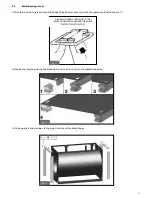
Page 21: ...LLA REGGIA IN PLASTICA PER FISSAGGIO DELLA LANA SUL FASCIAME DELLA CALDAIA fig 11 2 Prepare the staves by placing the 4 locking caps in each as shown in the explicative picture fig 12 3 Fix the uprigh...

Page 22: ...repared staves between the uprights and crossbars as shown in picture 15 fig 15 5 After all staves are positioned assemble the casing with self tapping screws fig 16 NOTE In the case of boilers with u...

Page 23: ...ossbar of the boiler Pass the cable through the opening shown see fig 17 fig 17 If the kit includes the staves for the panel completed with mounting holes and openings for all cables it is advisable t...

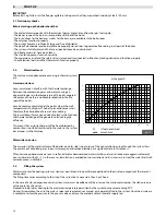
Page 24: ...f over heating The incrustations form a non conductive layer which reduces the thermal exchange of the generator diminishing the efficiency This means that a substantial part of the heat obtained by c...

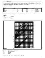
Page 25: ...s the boiler output in relation to the flue and air temperature and the percentage of carbon dioxide CO2 without however considering dispersion through the boiler casing Example Fuel DIESEL OIL Ambien...

Page 26: ...s and property The manufacturer advises the Customer to contact the manufacturer s Authorised Service Centres who are trained to perform the required maintenance and repair operations Before proceedin...

Page 27: ...End season maintenance or maintenance before long periods of inactivity In addition to the operations described above the following has to be performed Check the wear of the agitators to ensure their...

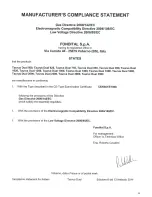
Page 28: ...28 8 DECLARATION OF CONFORMITY...

Page 29: ...29...

Page 30: ...30...

Page 31: ...31...

Page 32: ...32 ASSEMBLY INSTRUCTIONS FOR THE BOILER CONTROL PANEL...

Page 33: ...used with a bracket can be used for passing the capillary tubes through In case of need additional side slots B are present to host fittings model PG 21 not provided that can be used for the passage o...

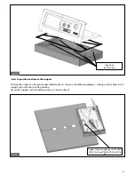
Page 34: ...then fix the control panel B onto the boiler as shown below fig 22 A C B C How to assemble the control panel plate Fix plate A onto the support B positioning the special gasket C as shown below Secure...

Page 35: ...pport on the pre mounted boiler panel as shown in the following diagrams making sure the holes in the support align with those in the panelling Secure the support with self drilling screws as shown in...

Page 36: ...36 fig 26 Support centring openings for other models fig 27 Openings for self drilling screws...

Page 37: ...7 How to mount the complete control panel Remove the right hand panel of the boiler and make the electrical connections fig 28 Mount the satellite cap and the right hand panel as shown in fig 29 fig 2...

Page 38: ...24 arrange for the electrical connections of the control panel 2 re install the satellite cap A fig 30 using the screws provided B fig 30 3 fix the pre assembled unit C of the control panel to bracket...

Page 39: ...39 fig 33 Control panel fixing fig 32 Openings for capillary tubes D E C fig 34 c c b Control panel fixing...

Page 40: ...Via Cerreto 40 25079 vobarno Brescia Italy Tel 39 0365 878 31 Fax 39 0365 878 304 e mail info fondital it www novaflorida it The manufacturer reserves the right to modify the products as it deems nec...

Reviews: