background image

User  Manual 


Acknowledgements 

Intel and Pentium are trademarks of Intel Corporation. 

Microsoft Windows and MS-DOS are registered trademarks of Microsoft Corp. 

All other product names or trademarks are properties of their respective owners. 


Safety Instructions 

1.


Read these safety instructions carefully. 

2.


Keep this User Manual for later reference. 

3.


Disconnect this equipment from any AC outlet before cleaning. Use a damp cloth. Do 

not use liquid or spray detergents for cleaning. 

4.


For plug-in equipment, the  power outlet socket must  be  located near the  equipment 

and must be easily accessible. 

5.


Keep this equipment away from humidity. 

6.


Put this equipment on a reliable surface during installation. Dropping it or letting it fall 

may cause damage. 

7.


The  openings  on  the  enclosure  are  for  air  convection.  Protect  the  equipment  from 

overheating. DO NOT COVER THE OPENINGS. 

8.


Make sure the voltage of the power source is correct before connecting the equipment 

to the power outlet. 

9.


Position the power cord so that people cannot step on it. Do not place anything over 

the power cord. 

10.


All cautions and warnings on the equipment should be noted. 

11.


If the  equipment  is not  used for a long time,  disconnect it from the power source  to 

avoid damage by transient overvoltage. 

12.


Never pour any liquid into an opening. This may cause fire or electrical shock. 

13.


Never open the equipment. For safety reasons, the equipment should be opened only 

by qualified service personnel. 


If one of the following situations arises, get the equipment checked by service 

personnel: 


The power cord or plug is damaged. 


Liquid has penetrated into the equipment. 


The equipment has been exposed to moisture. 


The equipment does not work well, or you cannot get it to work according to 

the user's manual. 

Summary of Contents for X12 Series

Page 1: ...User Manual User Manual X12 series 12 1 Fanless Multi touch Panel PC with Intel Celeron J1900 Processor...

Page 2: ...User Manual Record of Revision Version Issued Date Description Author v0 1 2016 5 6 First Release Jason...

Page 3: ...for air convection Protect the equipment from overheating DO NOT COVER THE OPENINGS 8 Make sure the voltage of the power source is correct before connecting the equipment to the power outlet 9 Positi...

Page 4: ...AME OR EQUIVALENT TYPE RECOMMENDED BY THE MANUFACTURER DISCARD USED BATTERIES ACCORDING TO THE MANUFACTURER S INSTRUCTIONS Safety Precaution Static Electricity Follow these simple precautions to prote...

Page 5: ...DD 14 3 3 Resistive Touch Setting 16 Chapter 4 BIOS Setting 19 4 1 Main 20 4 2 Advanced 21 4 2 1 CPU Configuration 22 4 2 2 Chipset Configuration 23 4 2 3 Storage Configuration 24 4 2 4 Intel R Smart...

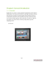
Page 6: ...advantage of desktop performance with low power consumption The fanless design increases reliability and the 7H surface hardness guarantees superior durability The X12 also supports two finger touch...

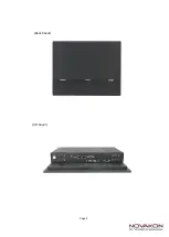
Page 7: ...Page 2 Back Cover I O Cover...

Page 8: ...ocessor System CPU Intel Celeron Processor J1900 Frequency 2 0 GHz 2 42 GHz Boost 4 Cores 4 Threads L2 Cache 2 MB System Chipset N A BIOS UEFI Memory Technology DDR3L 1333 MHz SDRAM Max Capacity 8 GB...

Page 9: ...either mSATA or full size Mini PCIe selected by jumper setting Power Power Supply Voltage Supports 9 36 V DC input Phoenix Connector Power Adaptor AC to DC 12 V 5 A 60 W DC output Power Input 9 36 V D...

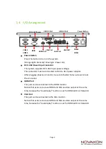
Page 10: ...lock the connector HDMI Port This port can be connected to the HDMI monitor Notice that users cannot use HDMI and VGA as video output at the same time because the dual display function is set for HDM...

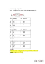
Page 11: ...5 NC 2 TX_D0 6 RX_D1 3 RX_D1 7 NC 4 NC 8 NC 1000BASE T Pin Definition Pin Definition 1 TX_D0 5 BI_D2 2 TX_D0 6 RX_D1 3 RX_D1 7 BI_D3 4 BI_D2 8 BI_D3 Activity Link LED Status Description Off No Link B...

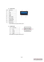
Page 12: ...Each USB3 0 port supports 900mA 5 V USB 2 0 Port Each USB2 0 port supports 500mA 5 V Pin Definition 1 5 2 USB 3 USB 4 GND 5 StdA_SSRX 6 StdA_SSRX 7 GND_DRAIN 8 StdA_SSTX 9 StdA_SSTX Pin Definition 1...

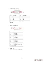
Page 13: ...DCD 6 DSR 2 RXD 7 RTS 3 TXD 8 CTS 4 DTR 9 RI 5 GND RS 232 Pin Definition Pin Definition 1 TX 6 N A 2 RX 7 N A 3 TX 8 N A 4 RX 9 N A 5 GND RS 422 Pin Definition Pin Definition 1 RTX 6 N A 2 N A 7 N A...

Page 14: ...inition 1 DCD 6 DSR 2 RXD 7 RTS 3 TXD 8 CTS 4 DTR 9 RI RS 232 GPIO Ports Option Pin Definition 1 SIO_GP1 2 SIO_GP2 3 SIO_GP3 4 SIO_GP4 5 SIO_GP5 6 SIO_GP6 7 SIO_GP7 8 SIO_GP8 9 VCC 12V default 5V Shie...

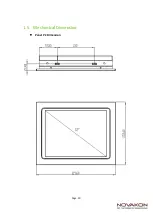
Page 15: ...Page 10 1 5 Mechanical Dimension Panel PC Dimension...

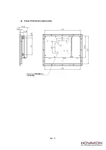
Page 16: ...Page 11 Panel PC Dimension Back side...

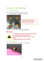
Page 17: ...itor to VESA Stand Warning 1 The length of VASA mount screw cannot exceed 5mm Calculated from monitor s back cover 2 Any wrong installation will cause monitor s great damage 3 The Spec of VASA mount s...

Page 18: ...e 12V DC power 5A MAX 3 0 40 degree C operating temperature Step 2 Connect another male plug of the power cord to an electrical outlet Step 3 Connect the Phoenix Connector Terminal into the system s P...

Page 19: ...Page 14 3 2 Installing 2 5 HDD Step 1 Loosen the 4 screws on the HDD Back Cover and open the cover HDD Back Cover...

Page 20: ...Pick up the HDD Bracket and Loosen tighten the 4 screws on it Step 3 1 Pick up the HDD Bracket and Loosen tighten the 4 screws on it 2 Install a new HDD and plug in SATA cable and SATA power cable No...

Page 21: ...ll driver in Windows 7 driver is automatically installed as a mouse device while in Vista 7 as a digitizer device You will see the difference that a icon shows up on the desktop without a icon in the...

Page 22: ...Page 17 Calibration 1 Please select a device then click Calibration You can also double click the Calibration start Setting...

Page 23: ...ation The display shows touch location Click Draw Test to start Touch the screen with your finger or a stylus and the drawing screen registers touch activity such left right up down pen up Clear Scree...

Page 24: ...on the computer the BIOS is immediately activated Pressing the Del key immediately allows you to enter the Setup utility When you enter the BIOS Setup utility the top of the screen has a menu bar with...

Page 25: ...Page 20 4 1 Main This section Main screen displays the system overview...

Page 26: ...llowing items CPU Configuration Chipset Configuration Storage Configuration Intel R Smart Connect Technology Super IO Configuration ACPI Configuration and USB Configuration USB Configuration Instant F...

Page 27: ...function please set this item to Enabled NOTE Enabling this function may reduce CPU voltage and lead to system stability or compatibility issues with some power supplies Please set this item to Disab...

Page 28: ...t to Enabled a VMM Virtual Machine Architecture can utilize the additional hardware capabilities provided by Vanderpool Technology 4 2 2 Chipset Configuration Share Memory This item allows users to co...

Page 29: ...s item allows users to enable or disable Deep S5 Auto will disable the deep S5 configuration if RTC LAN USB device power on settings enabled 4 2 3 Storage Configuration SATA Controller s This item all...

Page 30: ...Disk S M A R T This item allows users to enable or disable the S M A R T Self Monitoring Analysis and Reporting Technology 4 2 4 Intel R Smart Connect Technology Intel R Smart Connect Technology This...

Page 31: ...RS422 RS485 or Disabled COM2 Configuration This item allows users to enable or disable COM2 COM3 Configuration This item allows users to enable or disable COM3 COM4 Configuration This item allows user...

Page 32: ...or disable ACPI HPET Table Please set this option to Enabled if you plan to use this motherboard to submit Windows certification PCIE Devices Power On This item allows users to enable or disable PCIE...

Page 33: ...2 7 USB Configuration USB 3 0 Controller This item allows users to enable or disable the use of USB 3 0 controller Legacy USB Support This item allows users to select legacy support for USB devices T...

Page 34: ...SB flash drive floppy disk or hard drive then you can update your UEFI only in a few clicks without preparing an additional floppy diskette or other complicated flash utility Please be noted that the...

Page 35: ...item allows users to set CPU fan 1 s speed The default value is Full On CHA_FAN1 Setting This item allows users to set chassis fan 1 s speed The default value is Full On Case Open Feature This item al...

Page 36: ...unt Only the administrator has authority to change the settings in the UEFI Setup Utility Leave it blank and press enter to remove the password User Password Set or change the password for the user ac...

Page 37: ...is group Fast Boot Fast Boot minimizes your computer s boot time In fast mode you may not boot from an USB storage device Ultra Fast mode is only supported by Windows 8 and the VBIOS must support UEFI...

Page 38: ...pport Module CSM Enable to launch the Compatibility Support Module Please do not disable unless you re running a WHCK test If you are using Windows 8 64 bit and all of your devices support UEFI you ma...

Page 39: ...op out the following message Discard changes and exit setup Select OK to exit the UEFI SETUP UTILITY without saving any changes Discard Changes When you select this option it will pop out the followin...

Reviews: