


OnTime Clock
Installation and User Guide
Firmware Version 1
All claims based on information publicly available at time of printing. All other product or service names mentioned
in this document may be trademarks of the companies with which they are associated.
© 2015 Novanex, Inc. | All rights reserved | page 9
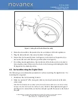
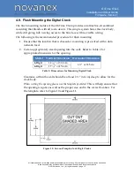
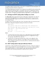
Figure 4: Analog Clock Double Mount Assembly
4.
Route the data cable to the junction box in accordance with local regulations.
5.
Plug the data cable into the connector (item 2 in Figure 4).
6.
Mount the clock assembly (item 3 in Figure 4) to the studs on the junction box
and secure the unit with the nuts provided (item 4 in Figure 4).
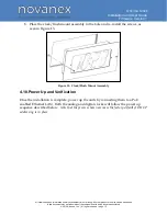
7.
For ceiling mount applications, the orientation of the clocks can be corrected by
removing the screws that secure the clocks to the housing and rotating the clock
90 degrees to the desired position.
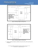
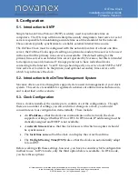
4.6. Surface Mounting the Digital Clock
The following is a recommended procedure for surface mounting the digital clock. No
mounting kit is required.
1.
Determine the clock mounting location.
2.
Mark two points 10” (25.4 cm) apart which are level and centered on the data
cable outlet.
Note that both models are mounted with a ten inch distance between screw hole centers;
however, the best location for the wall jack varies.
Refer to the templates in Figure 5
and Figure 6 to ensure that you line the wall jack up with the recess in the back of
the unit.


