- 9 -
NOVATEK-ELECTRO
REV-201М
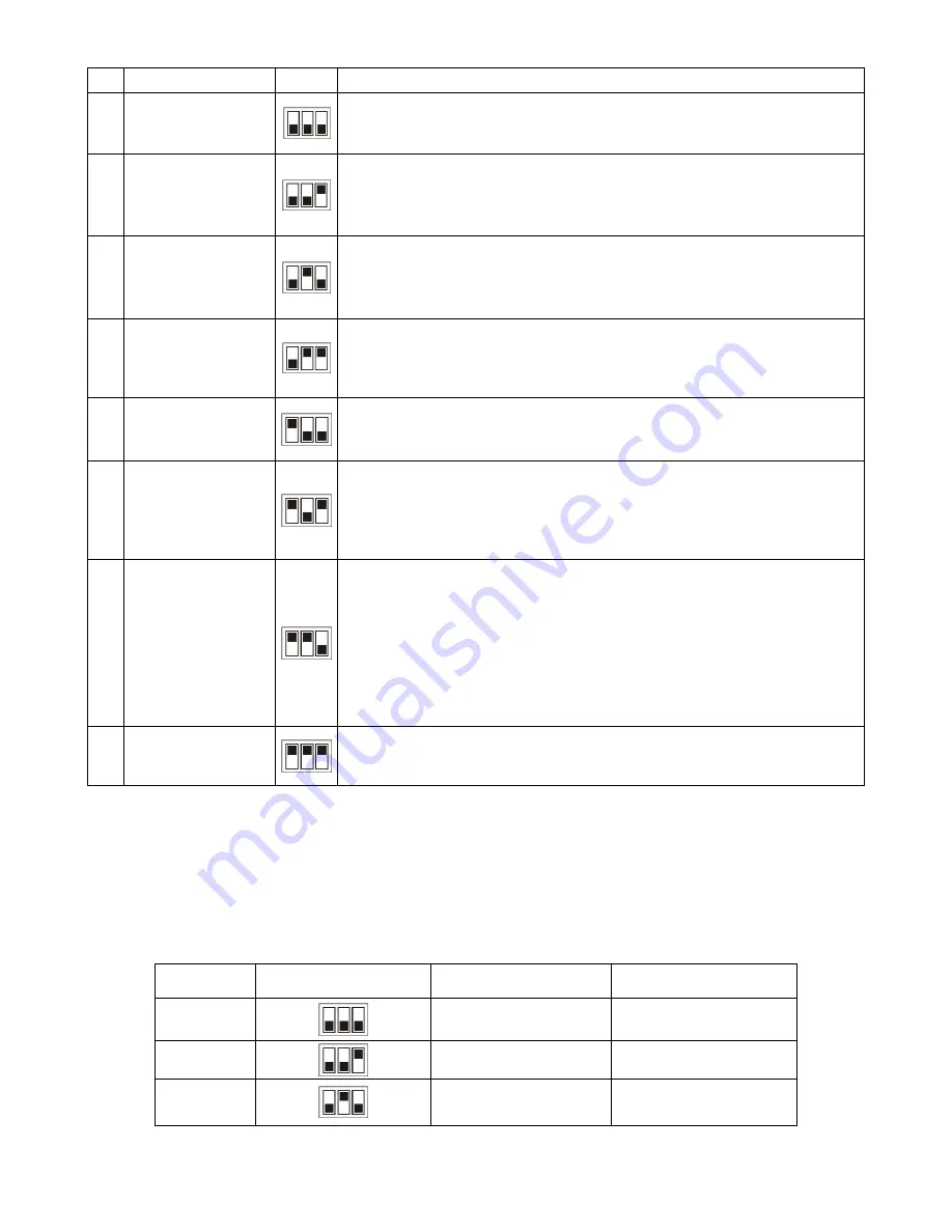
Table 2
№ OPERATION MODE
А
DESCRIPTION
1 Turn ON time delay
After the power supply application REV-201M performs user preset time
delay T1+T2 that will be followed by opening of the output contacts and
REV-201M will switch to idle state.
2 Impulse 1
After power supply application comes time delay interval adjusted by the
potentiometer knob
T2
, then the output contacts close for the time
T1
and
by the end of the
T1
time interval output contacts open and REV-201M
comes to idle state
3
Intermittent 1
After energizing the power supply the set time period T1 takes place, after the
end of set time period the relay contacts get closed for the set time period T2.
After the end of set time period T2 the relay contacts get open and the relay
restarts the program from the beginning.
4
Control mode
(pre-start signals)
After power supply application REV-201M output contacts close, then comes
fixed time interval of 10 seconds and output contacts open. Then comes new
fixed time interval of 30 seconds and output contacts close again for the time
of 30 seconds. Then contacts open and REV-201M switch to idle state.
5 Impulse 2
After energizing the power supply the relay contacts get closed for the set
time period T1+T2, After the end of set time period the relay contacts get
open and the relay switches over into the stand-by mode.
6
Intermittent 2
After energizing the power supply the relay contacts get closed for the set
time period T1. After the termination of this time interval T1 the relay
contacts get open and starts the timing countdown of set time interval T2.
After the termination of the T2 timing countdown REV-201M starts and the
process keep on working in cycle mode in this way further
7
Turn-off Delay
After voltage supplies to the second channel, the relay switches to the
standby mode (contacts of the first (1, 2) and the second (4, 5) channels
are open).
When voltage supplies to the first channel, timing of T1 + T2 of the first
channel is started. Upon completion of time-delay, the contacts (4, 5) of the
second channel are closed and
и the relay switches to the standby mode.
In case of power failure in the first channel, timing of T1 + T2 of the second
channel is started. Upon completion of time-delay, the contacts (4, 5) of the
second channel are open and the relay switches to the standby mode.
8 Reserved
After energizing the power supply the relay is in a stand-by mode. The LEDs
(1,6 figure 1) blink in red-green colors, the relay contacts are in the standard
open mode.
NOTICE:
When using the REV-201M in
Control operation mode
i
t doesn’t respond to any position or change of
the knobs position
D1
,
D2
as well as timing knobs
T1
,
T2
(see Figure 1).
2.1.2
Timing parameters adjustment.
Adjustment of time intervals should be made with the use of potentiometer knobs
10
,
12
(Figure 1) for the Channel
1 and potentiometer knobs
3
,
5
(Figure 1) for the Channel 2. Timing limits for the knobs are set up below with the use
of DIP switches
6
(Channel 1),
9
(Channel 2) (see Figure 1) in accordance with the Table 3:
Table 3
N
DIP switch position
(D1, D2)
Time intervals adjusted
by
Т1
Time intervals adjusted
by
Т2
1
0
– 1 sec
0
– 10 sec
2
0
– 10 sec
0
– 100 sec
3
0
– 100 sec
0
– 1 min


