background image

~ 37 ~ 

NOVATEK-ELECTRO   


UBZ-304


When disabling the load relay in the event of fault, UBZ records in its memory the code of the fault, the value of 

the parameter on which the fault occurred and time of occurrence. 


N o te  

 The fault time is determined by internal clock of UBZ.  


Number of simultaneously stored fault codes is 50. In case of subsequent faults occur, the fault information is 

recorded in place of the oldest fault 

To view the log, it is necessary to press button 

RES/MEM/SEL

Red LED 

SETUP

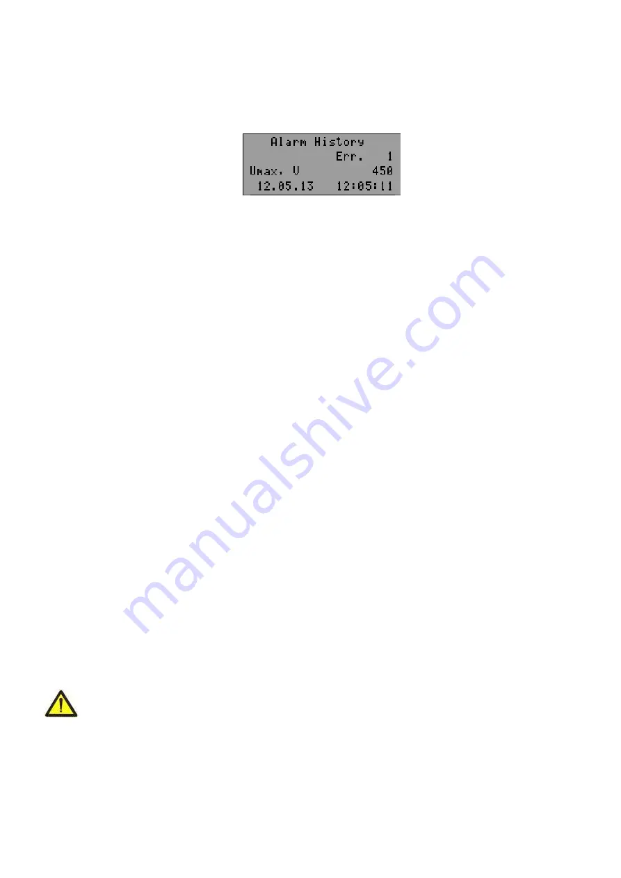
 will on in flashing mode, and UBZ indicators will display the latest fault (Fig.5.18). 


Line 1 

 indication of mode (alarm logbook); 

Line 2 

 number of the fault (1 

 means the most recent fault); 

Line 3 

 mnemonic of the fault as per Table 5.13 and the parameter value at the moment of the fault occurrence; 

Line 4 

 time and date of the fault. 


Figure 5.18


 Display in the view mode of the fault logbook 


View the fault logbook by pressing the 

UP

 or 

DOWN

 button. 

To exit the view log mode, press the button 

RES/MEM/SEL

 or exit will be automatically in 30 seconds after the 

last pressing of any button. 

Register addresses to read data log of faults via MODBUS Protocol are given in Table 5.9. 


5.7 MOTOR CONTROL ON UBZ FRONT PANEL 

Depending  on  the  value  of  the  parameter  “MotorOp  UBZ”,  you  can  control  the

  load  relay  of  UBZ  by 

simultaneously pressing the 

UP

 and 

DOWN

 buttons: 


“Off” 

- no reaction; 


“Start” (

motor start is enabled) - the load relay will enabled if ARS time has not finished; 


“Stop” (

motor  emergency  shutdown)  -  the load  relay  will  disabled  with  the issuance  of  fault  code 

“Stop 

nAR”).  

The restart of the motor is possible only after de-energizing and re-energizing of UBZ unit; 


“St<>” (

motor start and shutdown is permitted) - the load relay is disabled with issuance of code 

“Stop 

Motor”. 

To enable it, press again 

UP

 and 

DOWN

 buttons. 

N o te


 in case of selection of parameter 

“Start>power”= “

St

Off ” (

after energizing, start of the motor manually on 

the  front  panel  of  UBZ)  and 

“MotorOp UBZ”=


“Off” (

the  motor  control  manually  is disabled)  the load relay  will  not 

turn on. 


5.8 MOTOR CONTROL USING ANALOG INPUTS 

The motor control algorithms by the analog inputs "0-20 mA" and "0-10 V" are shown in Table 3.6.  
After the motor stopping according to emergency level the countdown for ARS will only start after going out the 

parameter value of the emergency zone. 

If  after  the motor  switching  off  by  the  alarm level  the  parameter  value is  between  the  levels  on and  off for  the 

motor, then: 

  green  LED "

Power relay

" blinks; 

  red LED "

FAULT

" is off; 

  the fault code is displayed on LCD. 

N o te


 In this state of UBZ it is possible to do early motor enabling by buttons on the front panel or by remote 

control. 


6 MAINTENANCE 

6.1 SAFETY PRECAUTIONS 

THE TERMINALS AND THE PRODUCT INTERNAL ELEMENTS CONTAINS POTENTIALLY LETHAL 
VOLTAGE. 

DURING MAINTENANCE IT IS NECESSARY TO DISABLE THE PRODUCT AND


CONNECTED DEVICES FROM THE MAINS 


Maintenance  of  the  unit  should  be  performed  by  persons  admitted  to  the  operation  and  have  the  appropriate 

permission. The recommended frequency of maintenance is every six months. 


6.2 MAINTENANCE PROCEDURE: 

  1) check the wires connection reliability, if necessary 

 clamp with force as specified in Table 3.1;  

  2) check visually the housing integrity; 
  3) if necessary, wipe with cloth the front panel and the unit housing. 

Summary of Contents for UBZ-304

Page 1: ...TRO LTD thanks you for purchasing our products You will be able to use properly the product after carefully studying the Operating Manual Keep the Operating Manual throughout the service life of the p...

Page 2: ...onnection 21 5 1 2 Selection of Current Transformers CT 21 5 1 3 General 21 5 1 4 Unit Installation 22 5 1 5 UBZ 304 connect 23 5 2 UBZ Control 24 5 2 1 Modes of UBZ control and status 24 5 2 2 Measur...

Page 3: ...dure 37 7 TRANSPORTATION AND STORAGE 38 8 SERVICE LIFE SHELF LIFE AND MANUFACTURER WARRANTY 38 9 ACCEPTANCE CERTIFICATE 38 10 CLAIMS DATA Appendix 39 CURRENT PROTECTION WITH DEPENDENT TIME DELAY Appen...

Page 4: ...OUNTING WORKS AND MAINTENANCE WITHOUT DISCONNECTING THE PRODUCT FROM THE MAINS TO OPEN AND REPAIR THE PRODUCT INDEPENDENTLY TO OPERATE THE PRODUCT WITH MECHANICAL DAMAGES OF THE CASE IT IS NOT ALLOWED...

Page 5: ...gn version UBZ provides continuous monitoring of mains voltage parameters current values of the phase line currents of three phase electrical equipment for 415V 50Hz and checking the resistance values...

Page 6: ...ltages and currents calibration factors is added Version 9 control algorithms by the engine on analog inputs are added 1 3 CONTROLS AND OVERALL DIMENSIONS Overall dimensions of UBZ are given in Fig 1...

Page 7: ...n the parameters setting mode 11 Button DOWN is scrolling of displayed parameters in the parameter view mode and scrolling of the menu in the parameters setting mode 12 Button RES MEM SEL is the param...

Page 8: ...oad VA not more 5 0 Weight not more kg 0 34 Overall dimensions Fig 1 1 H B L mm 110 96 88 3 Position in space free Housing material self extinguishing plastic Table 3 3 Characteristics of built in rel...

Page 9: ...ll drop lower than 1 2 In Maximum phase current achieved during this period is the maximum starting current 3 I t 3 I t 0 1 600 2 10 Start i Overload i Start time 42 43 44 Voltage Effective values of...

Page 10: ...d with MW MVA MVAr 5 If the temperature value exceeds specified limits then the indicator displays the alarm code in accordance with table 5 13 If the temperature sensor is disabled by software then t...

Page 11: ...sable 2 On AR protection is on ARS is enabled 161 Negative sequence current protection Actuation setting I2 rev tresh 5 20 10 It is set as percentage of rated current 162 Tripping delay s I2 rev delay...

Page 12: ...otec 0 2 2 0 Off protection is off 1 OnnAR protection is on ARS after tripping is disable 2 On AR protection is on ARS is enabled 179 Maximum line voltage V Umax tresh 330 450 415 180 Tripping delay f...

Page 13: ...t 0 2 0 0 Off protection is off 1 OnnAR protection is on ARS after tripping is disable 2 On AR protection is on ARS is enabled 194 Motor control and ARS ARS time after protection operation at minimum...

Page 14: ...abled 1 Pt100 of Pt100 type 2 Ni100 of Ni100 type 3 Ni120 of Ni120 type 204 Motor trip temperature Temp S2 Off M 0 220 180 205 Warning temperature Temp S2 Alarm 0 220 170 206 Temperature correction of...

Page 15: ...tional relay is enabled Timer value s Relay F time 0 300 30 See it 2 it 3 of the parameter Relay F mode address 214 215 Star delta mode Switching time s Delay RP RF 0 1 2 0 4 The time between the load...

Page 16: ...Version 9 The parameter value depends on software version 230 Indicator illumination1 Indicator L 0 2 1 0 Off illumination is off 1 On15s illumination is on for 15 s after pressing any buttons 2 On i...

Page 17: ...current factor to negative sequence voltage factor for thermal overload undercurrent protection in phases delayed starting rotor blocking overheating of windings for minimum line voltage for maximum...

Page 18: ...are assumed ARS after tripping will not occur regardless of the value of I2 rev protec parameter The coefficient of negative voltage current sequence is characteristic of unbalance of three phase vol...

Page 19: ...n you should enter the response time in case of double overload T2 the parameter of Thermal delay Current time characteristic with different values of T2 is given in Fig 3 4 For the standard recommend...

Page 20: ...751 and DIN 43760 3 4 9 Voltage protection In UBZ voltage protection before enabling the load it is necessary to check the corresponding set points and depending on their value the load relay enabling...

Page 21: ...upplier or manufacturer Carefully study the Operating Manual pay special attention to the connection diagram to power the product If you have any questions regarding the installation of the product pl...

Page 22: ...5 91 5 mm 0 5mm tolerance the distance between UBZ panels top bottom and side and the relevant surfaces of the panel should be at least 10 mm if it is assumed to have operational use of communication...

Page 23: ...insulation 23 to one of output contacts of MS If the motor housing is not grounded or network with isolated neutral is used or neutral wire is not connected to UBZ terminal it is necessary to connect...

Page 24: ...0 are closed when relay is off the contacts 16 17 and 20 21 are closed 5 2 UBZ CONTROL 5 2 1 Modes of UBZ control and status UBZ has five control modes Keyboard blocking MNS User level Advanced user l...

Page 25: ...g the keyboard no button is pressed within 15 s and setting of blocking has not been disabled by the user the keyboard is blocked again 5 2 4 Mode of Minimum number of settings MNS Mode of MNS is desi...

Page 26: ...play instead of the inscription OFF MMSP the inscription MMSP should remain The value of the parameter in the user mode can be changed if the fourth line of the indicator has only the inscription MMSP...

Page 27: ...s are restored advanced user password 123 This method does not recover the following settings the unit operating time Time UBZ operating time of the motor Time motor clock correction Correct Time Afte...

Page 28: ...simultaneously press UP and DOWN buttons 2 when Start Power St AR the load relay will be enabled after ARS time 3 when Start Power St 2s the load relay will be enabled within 2 seconds after energizin...

Page 29: ...er 0 1 2 3 4 5 6 7 ASCII code 30 Hex 31 Hex 32 Hex 33 Hex 34 Hex 35 Hex 36 Hex 37 Hex Character 8 9 A B C D E F ASCII code 38 Hex 39 Hex 41 Hex 42 Hex 43 Hex 44 Hex 45 Hex 46 Hex In RTU mode 8 bit dat...

Page 30: ...t changed but the format of the transmission data and control of data is based on the Table 5 4 Table 5 4 Data packet in ASCII mode Name Description STX Start character 3A Hex ADR1 UBZ communication a...

Page 31: ...operation day Time UBZ 217 Motor operating time day Time motor 218 Access code of user Users code 219 Access code of advanced user Password 220 Restoration of factory settings Default Factor 221 The u...

Page 32: ...mitting device In case of mismatching the generated and received Cyclic Redundant Check the error message will be generated The field of Cyclic Redundant Check has two bytes CRC in the message is tran...

Page 33: ...l relay operation 00 alarm relay 01 time relay 10 star delta Bit 6 0 MNS mode is disabled 1 MNS mode is enabled Bit 7 0 clock battery is normal 1 the clock battery should be replaced Bit 8 0 normal op...

Page 34: ...and The master should repeat the message later when the slave is freed 07h NEGATIVE ACKNOWLEDGE UBZ cannot perform the program function received in request 5 4 9 Remote control of the motor using RS 2...

Page 35: ...the command UBZ RESTART the delay of at least 100 ms should be provided ATTENTION WHEN THE MOTOR IS ENABLED THE FULFILLMENT OF COMMAND UBZ RESTART RESTART IS DISABLED 5 4 12 UBZ factory settings using...

Page 36: ...alance 314 14 901 14 Minimum insulation resistance of motor winding Insul Res Insulation resistance 315 15 901 15 Mains minimum frequency F min Frequency 316 16 902 0 Mains maximum frequency F max Fre...

Page 37: ...fault code Stop nAR The restart of the motor is possible only after de energizing and re energizing of UBZ unit St motor start and shutdown is permitted the load relay is disabled with issuance of co...

Page 38: ...he unit operation is 5 years from the date of sale During the warranty period the Manufacturer is responsible for free repair of the unit if the Consumer has complied with the requirements of this Ope...

Page 39: ...39 NOVATEK ELECTRO UBZ 304 Appendix CURRENT PROTECTION WITH DEPENDENT TIME DELAY mandatory...

Page 40: ...40 UBZ 304 NOVATEK ELECTRO...

Page 41: ...g over and the motor insulation control When UBZ is in the star delta mode it is allowed performing the motor control in the following ways the motor disabling enabling using the external automatic st...

Reviews: