


~ 8 ~
UBZ-304
NOVATEK-ELECTRO
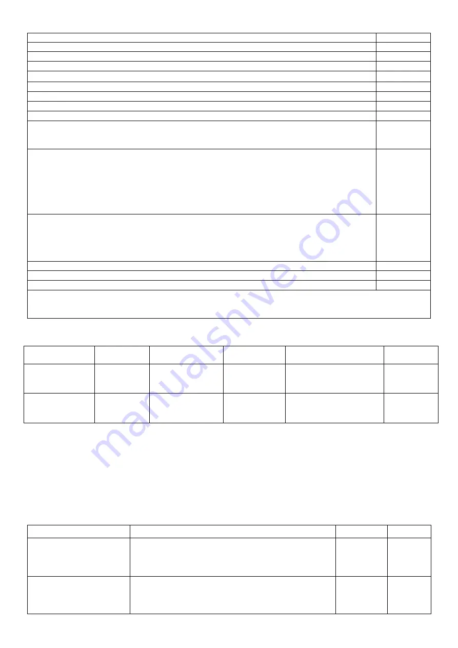
Table 3.2
–
Technical Specifications
Description
Value
Operating supply voltage, three-phase
415 V, 50 Hz
Mains frequency, Hz
48-62
Rated current of CT, A
5
(Phase/line) voltage hysteresis, V
10/17
Heat hysteresis, in % of accumulated heat in case of shutdown
33
Determination accuracy of trip threshold for current, not more, in % of rated value
2
Determination accuracy of trip threshold for voltage, not more, V
3
Determination accuracy of out-of-phase voltage, not more, V
3
Voltage when maintaining serviceability:
- phase voltage, when powered by one phase and zero wire is connected, not less, V
- line voltage, when powered by three phases, not more, V
180
450
Analog inputs:
- input to connect temperature transmitter (types: Pt100, Ni100, Ni120), pc.;
- input to connect temperature transmitter of PTC-1000 type, pc.;
- three analog inputs for standard CT with 5A output (T-0.66 type or similar), pc.;
- input to connect differential current transformer (zero sequence transformer) pc.;
- input to measure current of 0-20 mA, pc.;
- input to measure voltage of 0
–
10 V, pc..
1
1
3
1
1
1
Main outputs:
–
-load relay
–
two groups of changeover contacts to control the electric motor starter
–
8
A, 250 V at
cos φ=1;
–
functional relay
–
one group of changeover contacts - 16A, 250V at
cos φ=1 (
function of
the relay is set by the user).
Permit according to temperature of temperature transmitters,
°С
1
Power consumption (under load), VA, not more
5.0
Weight, not more, kg
0.34
Overall dimensions (Fig.1.1), H*B*L, mm 110*96*88,3
Position in space free
Housing material self-extinguishing plastic
Table 3.3
–
Characteristics of built-in relay output contacts
Relay
Max. current
at U~250V
Number of
actuations
х1000
Max. switching
power
Max. continuous
boosting AC / DC voltage
Max. current
at U
cont
=30V
Functional relay
Cos
= 0.4
Cos
= 1.0
5
А
16А
100
100
4000 V
А
440/300 V
5
А
Load relay
Cos
= 0.4
Cos
= 1.0
2
А
8
А
100
100
2000 V
А
460 V
3
А
3.2 MEASURED, CALCULATED, SPECIAL AND SERVICE PARAMETERS
Special and service parameters are intended only for transmission using MODBUS interface
(RS-485/RS-232). Special and service parameters are given in Table 3.4.
Measured and calculated parameters the values of which are displayed on LCD display, limits of their
measurements and accuracy are given in Table 3.5.
Parameter values can be transferred to PC connected to one of the UBZ interfaces (MODBUS, RS-232).
Parameter addresses are indicated in Table 3.5.
Table 3.4
–
Special and Service Parameters
Measurement functions
Range
Remarks
Address
Heat balance of the motor
Read-only parameter of
RS-232, RS-485 interface
The number 1100000 corresponds to 100% of
accumulated heat at which the motor is switched off
when the thermal overload protection is enabled (it
2.4.7)
Read-only
parameter
73,74
Index of the last fault in
the fault logbook
It varies from 0 to 49, increasing by one after recording
another fault in the fault logbook. When the quantity of
faults will reach 50, the count of faults will begin again
from scratch.
Read-only
parameter
75


