5
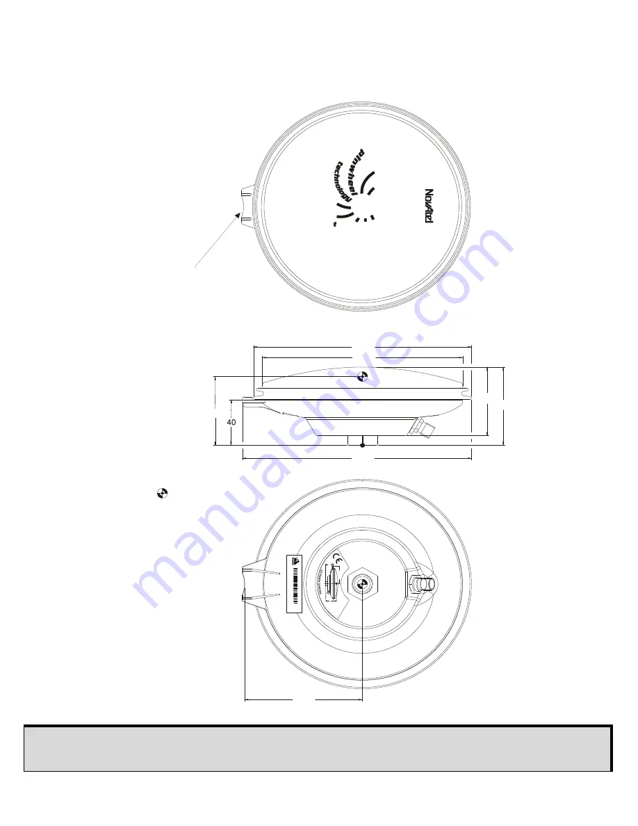
MECHANICAL DRAWINGS
Height = Vertical phase center offset from antenna reference point or antenna reference plane
(ARP)
TOP
VIEW
BOTTOM
VIEW
100
60.6
69.1
Ø
185
Ø
170
194.5
SIDE
VIEW
Height
All dimensions are in millimeters (mm)
where 1 inch = 25.4 mm
= PHASE CENTER
Tape measure
station
H
/W
R
ev:
1
.00
P
/N
: 010
1xxxx
M
A
D
E
IN
C
A
N
A
D
A
w
w
w
.n
ov
ate
l.c
a
NVH9
99
99999
G
PS
-70x A
N
T
E
N
N
A
ARP
100 m
m
40
mm
AR
P
4.5
-1
8 V
D
C
50
m
A m
ax
.
65
m
m
Summary of Contents for GPS-703-GGG
Page 3: ...3 ELEVATION GAIN PATTERN...


