6
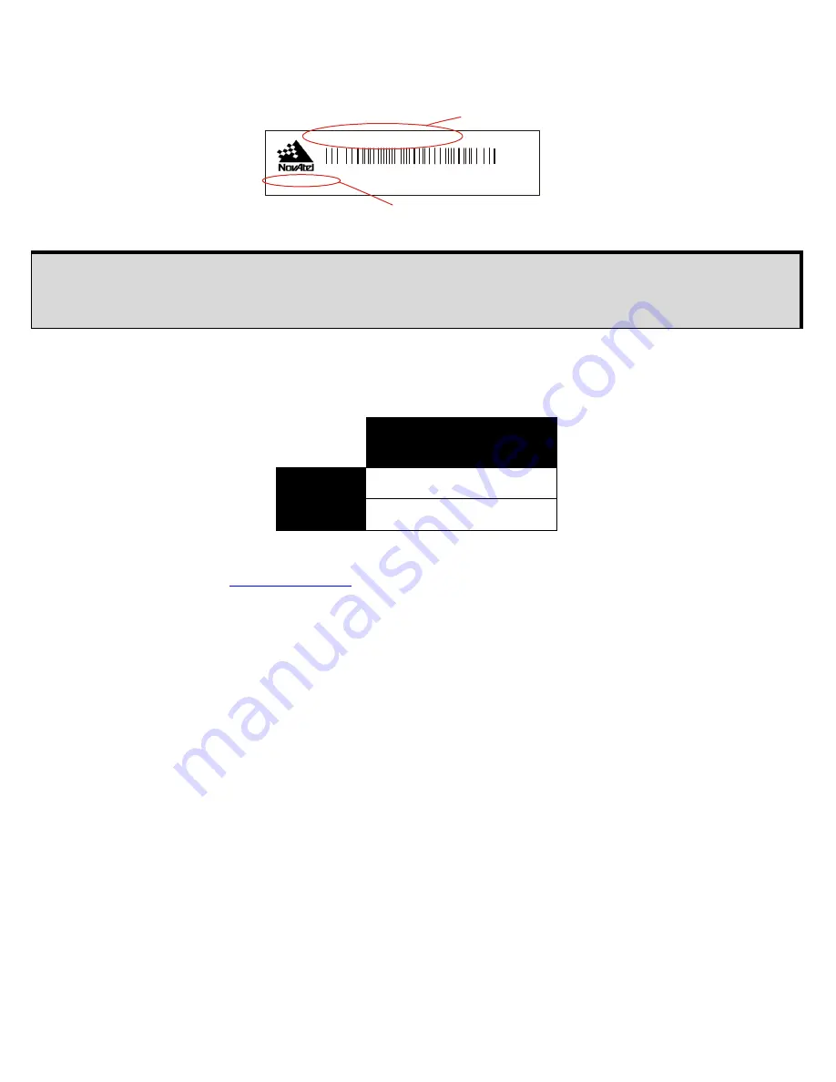
Refer to the
Mechanical Drawings
on the previous panel and the close-up of the label below before reading
this section.
Table 1
shows typical absolute and relative offset numbers for the current GPS-703-GGG antenna model.
Table 1: Phase Center Offset
For absolute and relative offset values for phase center variation (PCV tables are available for download),
visit the GEO++ website at
www.geopp.com
.
If you need any further advice on this matter, visit our website at
www.novatel.com
. Other methods of
contacting Customer Service can be found on the last panel of this guide.
Only integer hardware revisions affect the phase center offsets. For example, the numbers
given for hardware revision 2.02 are applicable to an antenna labelled H/W Rev: 2.00, 2.04,
2.12 and so on.
Absolute (GEO
++
)
Height
L1
61.5 mm
L2
58.68 mm
H/W Rev: 1.00 P/N: 0101xxxx
MADE IN CANADA www.novatel.ca
NVH99999999
GPS-70x ANTENNA
Antenna model
Hardware Revision
Summary of Contents for GPS-703-GGG
Page 3: ...3 ELEVATION GAIN PATTERN...


