background image

8

novatelwireless.com

LEDs

The MT 4000 includes LEDs to indicate Power, GPS, and Registration status.

Figure 2-1 MT 4000 LEDs

The MT 4000 has three LEDs on its front panel to indicate the following:

MT 4100 LEDs

PWR:

Indicates power to the GPS module. LED is on ~1 second after powered on and the GPS module is
operational. LED is off when powered off or when the MT 4000 enters Low-Power Sleep mode.
Note: If you disable the GPS module, you must apply power for this LED to turn on.

GPS:

You can configure this LED to display registration, GPS fix status, or other user functions. By default,
this LED indicates GPS fix status. The LED remains off when it receives invalid GPS data. The LED
remains on when it receives valid GPS data.

Registration:

You can configure this LED to display registration or other user functions. By default, this LED indic-
ates GSM registration status. If LED stays off, this indicates that the device is not attempting to
register to the network. If LED blinks, this indicates that the device is trying to connect to the net-
work. If LED is always on, this indicates that the device has connected to the network.

Summary of Contents for GSM2448UG001

Page 1: ...GSM2448UG001 MT 4000 User Guide Version 1 03 16 October 2013...

Page 2: ...ranty or representation with respect to the merchantability suitability functionality accuracy or completeness of any such New Materials The user of such New Materials assumes all risk known or unknow...

Page 3: ...d into a retrieval system or transmitted in any form or by any means electronic mechanical photocopying recording or otherwise or for any purpose without the express written permission of Novatel Wire...

Page 4: ...bstantially in accordance with the product documentation provided by Novatel Wireless M2M Novatel Wireless M2M does not warrant that a the product hardware or firmware will meet the purchaser s requir...

Page 5: ...ser notifies Novatel Wireless M2M in writing during the warranty period Novatel Wireless M2M from time to time and in its sole discretion may make available for download on its website www novatelwire...

Page 6: ...NOVATEL WIRELESS HAS BEEN ADVISED OF THE POSSIBILITY OR LIKELIHOOD OF SUCH DAMAGES Some jurisdictions may require a longer warranty period than specified above and accordingly for products sold in th...

Page 7: ...in a particular installation RF EXPOSURE Your device is a radio transmitter and receiver It is designed and manufactured not to exceed the emissions limits for exposure to radio frequency RF energy se...

Page 8: ...comply with the European Union Restriction of the Use of Certain Hazardous Substances in Electrical and Electronic Equipment RoHS Directive 2002 95 EC effective since July 1 2006 DISCLAIMER The infor...

Page 9: ...ts l Do not connect two or more of the contacts l Do not disassemble destroy or attempt reassembly of the battery l Do not place or leave the battery in a damp or wet environment l Do not allow water...

Page 10: ...tal 3 Components 4 Protocols 4 Part Numbers 4 Document References 5 Certifications 5 Additional Features 5 2 Features And Functions 6 GPS 7 GPS Measurements 7 LEDs 8 22 Pin IO Connector 9 The 1 Wire I...

Page 11: ...pening The Device 17 Inserting The SIM 18 Closing The Device 19 Device Installation 21 Device Mounting 22 Mounting Methods 22 Device Orientation 23 4 Network Test Procedure 25 Configuring The Modem 26...

Page 12: ...1 novatelwireless com 1 Introduction Description Technical Specifications...

Page 13: ...s teen tracking vehicle location and recovery and more The MT 4000 is designed for application providers system integrators and enterprise customers to optimize mobile resources and improve their bott...

Page 14: ...g Voltage 9 32 V DC operational for 12 V 24 V systems Power Consumption on page 12 Radio Technology Quad band 850 900 1800 1900 MHz Downlink Uplink 56 6 kbps 14 4 kbps Class 4 2W 850 900 MHz Class 1 1...

Page 15: ...GPS red Analog To Digital Converter ADC1 10 bit 0 16V input range 1 40V max scaling 0 0156 per bit 16vd c 1023 Analog To Digital Converter ADC2 ADC2 10 bit 0 32V input range 1 40V max scaling 0 0312...

Page 16: ...Application Note ENF0000CB001 API Reference ENF0000XG001 GFMI Technical Guide ENF0000AN014 Access the Novatel Wireless M2M Test Server ENF0000AN010 MT Decoding NMEA Messages ENF0000AN018 1 Wire Interf...

Page 17: ...6 novatelwireless com 2 Features And Functions GPS LEDs 22 Pin IO Connector The 1 Wire Interface Power Accelerometer Device Check in Optional Software Features...

Page 18: ...ets please see Novatel Wireless M2M Application note ENF0000AN010 For more details on Virtual Odometer please see Novatel Wireless M2M document ENF0000CB001 API Reference For more details please see N...

Page 19: ...LED to turn on GPS You can configure this LED to display registration GPS fix status or other user functions By default this LED indicates GPS fix status The LED remains off when it receives invalid G...

Page 20: ...ould not be applied 11 Ignition Sense Vehicle Ignition Sense 12 MIC Microphone Note Although this signal is AC capacitively coupled to the modem there is a 1K Ohm res istor to ground with a power rati...

Page 21: ...e Power from 12 or 24 V Vehicles 19 Digital Input 3 Digital Input 3 GPI10 20 RS 232 RTS RS 232 RTS In Note 25 VDC to 25 VDC 21 RS 232 TX RS 232 TX In Note 25 VDC to 25 VDC 22 RS 232 RX RS 232 RX Out N...

Page 22: ...l Up Down Minimum High input threshold VIH 6 1 Vdc 8 9 19 Digital Input 1 2 3 GPI 1 GPI 9 GPI 10 Digital Inputs with selectable Pull Up Down Maximum Low input threshold VIL 0 39 Vdc 8 9 19 Digital Inp...

Page 23: ...2 V and 24 V vehicles per SAE specifications This also protects 24 V vehicles when you need to jump start them Pins 17 and 18 on the 22 Pin IO connector are the power input and pins 6 and 7 are ground...

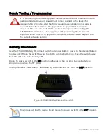
Page 24: ...vice will respond with an error If the upgrade is complete the device will respond with the current software version Battery Disconnect Use the MT 4000 Battery Disconnect Switch to remove battery powe...

Page 25: ...r second l Filter Coefficient and Filter Bandwidth l Device Orientation Setup For more information please refer to Novatel Wireless M2M document ENF0000AN003 Accelerometer Guide Application Note Devic...

Page 26: ...face GFMI GFMI provides the MT 4000 with a Wireless Network back end to allow the Garmin Portable Navigation Device PND to communicate with a server Garmin has defined and published the GFMI Control S...

Page 27: ...16 novatelwireless com 3 Installation SIM Card Access Device Installation Device Mounting Device orientation...

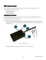
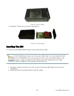
Page 28: ...o prevent damaging the device use the Metal Lever Novatel Wireless M2M part number K1T2418 when opening the MT 4000 To open the MT 4000 follow these steps 1 Insert the curved foot of the Metal Lever i...

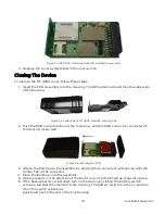
Page 29: ...000 device does not come with a SIM card You must obtain the SIM from the GSM GPRS service provider and have it provisioned for data by the operator Always protect the SIM Without the SIM installed th...

Page 30: ...f the red arrow until the PCB comes into contact with the Housing inside wall Figure 3 6 Inserting the PCB 3 Attach the End Cap to the assembly by aligning the Connector Tab Opening with the Center Ta...

Page 31: ...20 novatelwireless com Figure 3 7 Assembled Device...

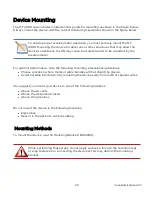
Page 32: ...e connected first Failure to connect ground to the MT 4000 before connecting auxiliary devices may result in damage to the attached I O device Figure 3 8 MT 4000 Mounting Anchors Before connecting to...

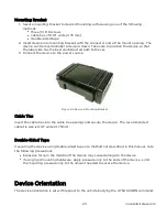
Page 33: ...he following mounting precautions guidelines l Choose a location where metal or cable bundles will not shield the device l Avoid possible interference by mounting the device away from radio or speaker...

Page 34: ...ower source Figure 3 9 Device in Mounting Bracket Cable Ties Insert the cable ties into the cable tie openings and secure the device The recommended cable tie size is 0 19 wide 4 75mm Double Sided Tap...

Page 35: ...e used to convert the accelerometer axes to the vehicle axes so that acceleration and deceleration along the vehicle centerline front to back can be measured separately from the side to side and up an...

Page 36: ...25 novatelwireless com 4 Network Test Procedure Configuring the Modem Verifying Server Connectivity...

Page 37: ...apitest nvtl com UDPAPP l Remote Server IP port 1721 Ensure the device is powered up and connected to the PC using serial connection or USB whichever is applicable for the device you are using You wi...

Page 38: ...Checking if the device can connect to the cellular network Once the device is power cycled as per the AT RESET in Step 2 The following commands can be used to check that the device can connect to the...

Page 39: ...th a specific server AT UDPAPI 1721 Configure the port number to be used by the modem AT WAKEUP 1 1 Enable wakeup to be sent to the server every 60 seconds AT W Giving the modem a unique name using AT...

Page 40: ...gure 4 1 apitest enfora com enforaapp Window 2 Enter the Server port in the port command box In this case it is 1721 as defined in AT UDPAPI 1721 3 Enter the name used in the Modem ID MDMID command in...

Page 41: ...you should see a wakeup message in the window Selecting the Clear button will erase the contents from the ASCII Data window 6 Enter the following command in the Command Data text box ATI 7 Click on th...

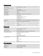
Page 42: ...31 novatelwireless com 5 Accesories Mounting Bracket Cables...

Page 43: ...n Development Cable CAB2448 02 Power Ground Ignition Cable CAB2448 01 Mounting Bracket Use the Mounting Bracket to securely mount the device For more information on mounting see the Device Installatio...

Page 44: ...igure 5 2 22 pin Cable Connector Power Cable The power cable for the MT 4000 CAB2448 01 includes a fuse and ignition sense Figure 5 3 Power Cable The connector pin out on the cable is shown below Figu...

Page 45: ...and testing the device It contains an RS232 interface I O header and audios leads Figure 5 5 Cable Schematic The Serial To DB9 Wiring Guide Connector DB9 Wire Color 6 7 Ground 5 Ground Orange 22 Rx 2...

Page 46: ...s com 3 1 1 Wire I F 4 2 ADC In 2 5 3 ADC In 1 8 4 Digital Input 2 9 5 Digital Input 1 14 6 Digital Output 2 15 7 Digital Output 1 16 8 Digital Output 3 19 9 Digital Input 3 NC 10 No Connect 18 11 Pow...

Reviews: