D
Functional Overview
GPS/GLONASS Receiver User Manual Rev 1
57
recommended.
NovAtel offers the 504 and 514 model antennas to work with your MiLLennium-GLONASS GPSCard system.
Both antennas use low-profile microstrip technology and include band-pass filtering and an LNA. The GPS/
GLONASS antenna you choose will depend on your particular application. The NovAtel antennas available to
work with your MiLLennium-GLONASS GPSCard system are single-frequency models, and each of these models
offers exceptional phase-center stability as well as a significant measure of immunity against multipath
interference. Both models have an environmentally-sealed radome.
NovAtel also offers high-quality coaxial cable in standard 5 (Model C005), 15 (Model C015) and 30 m (Model
C030) lengths. These come with a TNC male connector at each end. Should your application require the use of
cable longer than 30 m you will find the application note Extended Length Antenna Cable Runs at our website,
http://www.novatel.ca, or you may obtain it from NovAtel Customer Service directly, see Page 7.
While there may be other coaxial cables and antennas on the market which may also serve the purpose, please note
that the performance specifications of the MiLLennium-GLONASS GPSCard are warranted only when it is used
with NovAtel-supplied accessories.
D.1.2 PRINCIPAL POWER SUPPLY
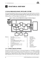
A single external power supply (4.875 - 5.250 V DC) is all that is necessary to meet the MiLLennium-GLONASS
GPSCard’s 8 W (typical) power consumption.
D.1.3 OPTIONAL LNA POWER SUPPLY
The MiLLennium-GLONASS GPSCard provides power to its GPSAntennas out of the primary 5 V DC input.
However, if a different type of antenna is required that is incompatible with this supply, then you could connect an
additional power source (
≤
30 V DC, 100 mA maximum and user-supplied) to the MiLLennium-GLONASS
GPSCard. In either case, the power is fed to the antenna through the same coaxial cables used for the RF signals.
D.1.4 RADIO FREQUENCY (RF) SECTION
The MiLLennium-GLONASS GPSCard receives partially filtered and amplified GPS and GLONASS signals from
the antenna via the coaxial cable. The RF section does the following:
•
filters the RF signals to reduce noise and interference
•
down-converts (with further band-limiting) the RF signals to intermediate frequencies (IFs)
that are suitable for the analog-to-digital (A/D) converter in the digital electronics section
•
amplifies the signals to a level suitable for the A/D converter in the digital electronics
section
•
receives an automatic gain control (AGC) input from the digital signal processor (DSP) to
maintain the IF signals at a constant level
•
supplies power to the active antenna through the coaxial cable while maintaining isolation
between the DC and RF paths. A hardware jumper configuration is provided to select an
internal or external DC power supply for the active GPS/GLONASS antenna.
The RF section can reject a high level of potential interference (e.g., MSAT, Inmarsat, cellular phone, and TV sub-
harmonic signals).
D.1.5 DIGITAL ELECTRONICS SECTION
The digital section of the MiLLennium-GLONASS GPSCard receives down-converted, amplified combined GPS/
GLONASS signals which it digitizes and processes to obtain a GPS solution (position, speed, direction and time).
The digital section consists of an analog-to-digital converter, a 32-bit 25 MHz system processor, memory, control
and configuration logic, signal processing circuitry, serial peripheral devices, and supporting circuitry. I/O data and
timing strobe signals are routed to and from the board via a 64-pin DIN 41612 Type B male connector. Two EIA
RS-232C serial communications ports support user-selectable bit rates of 300 - 115,200 bps, with a default of 9600
bps. The digital section does the following:
•
converts the IF analog signals to a digital format
•
tracks the C/A codes and carrier phases of the satellites in use
•
performs channel and loop control
•
performs position computation


