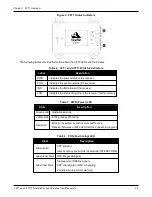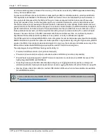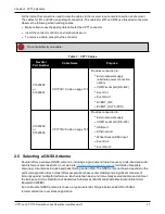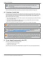
Chapter 2 CPT7 Installation
CPT7 and CPT7700 Installation and Operation User Manual v12
31
5. Connect power to the CPT7.
See
on page 38 for details.
6. Connect a data communication device, such as a computer, to the CPT7. A data communication device is
used to configure and monitor the receiver.
See
Connect the CPT7 to Data Communication Equipment
on page 36 for details.
2.9 Mounting the GNSS Antenna
The CPT7 is designed to operate with any NovAtel GNSS antenna. See
page 27 for more information.
When installing the antenna:
l
Choose an antenna location with a clear view of the sky so each satellite above the horizon can be tracked
without obstruction. For more information on RF signal propagation and multipath, refer to the NovAtel
application note
APN-008: Discussions on RF Signal Propagation and Multipath
at
novatel.com/support/support-materials/application-notes
.
l
Mount the antenna on a secure, stable structure capable of safe operation in the specific environment.
l
Ensure the antenna cannot move due to dynamics.
l
For dual antenna systems only
Heading accuracy is dependent on antenna baseline length. Mount the primary and secondary antennas
as far apart as possible. A minimum separation distance of 1 meter is recommended.
For more detailed information about GNSS antenna installation, refer to
APN-077: RF Equipment Selection
at
novatel.com/support/support-materials/application-notes
.
2.9.1 Antenna LNA Power
NovAtel antennas and coaxial cables meet receiver RF input gain requirements. NovAtel coaxial cables are
designed to introduce no more than 10 dB loss and NovAtel antennas are equipped with built-in LNAs that
provide 29 dB of gain to the satellite signal received.
The power to the antenna LNA is provided through the receiver’s RF port center conductor.
The CPT7 pr5 VDC ±5% at a maximum of 200 mA.
Antenna supply over current protection limits the LNA power.
If a short circuit or other problem causes an overload of the current supplied to the antenna, the
receiver hardware shuts down the power supplied to the antenna. To restore power, power cycle the
receiver. The Receiver Status word, available in the
RXSTATUS
log (see
), provides more information about the cause of the problem.
2.10 Mount the CPT7
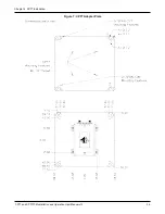
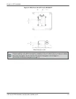
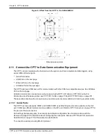
Mount the CPT7 in a fixed location where the distance from the CPT7 to the phase center of the GNSS
antennas is constant. Ensure that the orientation with respect to the vehicle and antennas is also constant.


