Chapter 10 Troubleshooting
CPT7 and CPT7700 Installation and Operation User Manual v12
136
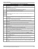
Bit Set
Action to Resolve
0
Check the Error Word in the
RXSTATUS
log. See also
Table 22: Resolving a Receiver Error Word
1
Check the temperature ranges in
l
CPT7 Electrical and Environmental Specifications
2
See
Power Supply Requirements for the CPT7
3
See
4
5
6
7
Check the CPU idle time. Check for unnecessary logging. Check for simultaneous use of
functionality.
8
See
Table 9: Serial Ports Supported
Also, check the Auxiliary 2 Status word to determine which COM port has overrun its buffer.
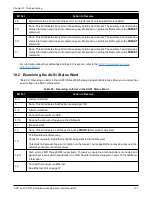
9-11
Reserved
15
Check the Auxiliary 1 status word to determine which RF channels are jammed.
16-17
Reserved
18
When the receiver has tracked GNSS satellites long enough for a valid almanac to be received, this
bit will be set to 0.
19
None. This bit only indicates if the receiver has calculated a position.
20
None. This bit is a status bit indicating if the receiver’s position has been manually fixed and does not
represent a problem. Refer also to the
FIX
command.
21
None. This bit indicates if clock steering has been manually disabled. Refer also to the
FRESET
command.
22
None. This bit only indicates if the clock model is valid. Refer also to the
FRESET
command.
23
None. This bit indicates if the phase-lock-loop is locked when using an external oscillator. Refer also
to the
FRESET
command.
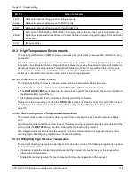
24
Check the CPU idle time. Check for unnecessary logging. Check for simultaneous use of
functionality.
25-26
None. These bits identify the receiver family. For OEM7 receivers, bit 25 is set to 1 and bit 26 is set to
zero.
27
Interference Toolkit HDR mode status. When this bit is set to 1, Interference Toolkit HDR mode is
enabled.
Table 23: Resolving an Error in the Receiver Status Word

