background image

Chapter 11   NovAtel Firmware

CPT7 and CPT7700 Installation and Operation User Manual v12

145

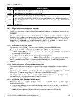
11.4.3 Downloading Firmware

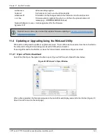
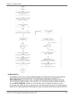
1. Select the file to download according to

Open a File to Download

on page 143.

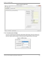
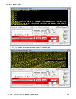
2. Ensure the file path and name are displayed in main display area (see

Figure 46: Open File in WinLoad

on

the previous page).

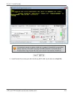
3. Click

Write Flash

to download the firmware.

4. When

Searching for card

appears in the main display, power cycle the receiver.

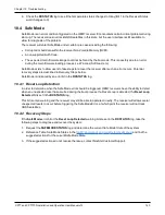
5. If the Authorization Code window appears, enter the auth-code and click

OK

. See

Authorization Code

on

page 141 for further information about the Authorization Code.

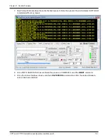
6. The receiver finishes the download and then resets. The process is complete when

Done

appears in the

main display area.

7. Close WinLoad.

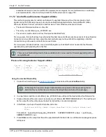
If loading a firmware that is currently installed on a receiver (i.e. reloading the same version of
firmware on a receiver), ensure that

Optimized Loading

option is unchecked in WinLoad under

Settings

|

Options

|

Optimized Loading

.

11.5 Updating the Firmware Using NovAtel Application Suite

To use NovAtel Application Suite to update the receiver firmware, the receiver must be connected to the
computer running NovAtel Application Suite using a serial (COM) port, USB port or Ethernet port.

To update the firmware on the receiver:

1. Obtain the new firmware file.

See

Downloading Firmware Files

on page 142 for information about obtaining the latest version of

receiver firmware.

Copy the firmware file to the computer's local drive before uploading.

2. Connect a computer to the receiver using a serial (COM) cable, USB cable or Ethernet connection.

3. Start NovAtel Application Suite on the computer.

4. Use NovAtel Application Suite to connect to the receiver.

For information about using NovAtel Application Suite, refer to

docs.novatel.com/Tools

.

5. On the

Status and Configuration

window, click the

Device

menu and select

Update

.

The

Update

window appears.

6. Click the

Browse

button.

7. Navigate to the directory that contains the new firmware file and select the file.

8. Click the

Open

button.

The Update window appears with the name of the selected file in the Select File field.

9. Click the

Apply

button.

After the new software is loaded, the receiver will restart.

Summary of Contents for NEXAGON CPT7

Page 1: ...CPT7 and CPT7700 Installation and Operation User Manual CPT7 and CPT7700 Installation and Operation User Manual v12 August 2022...

Page 2: ...el warranty and return policies Proprietary Notice ALIGN GLIDE Inertial Explorer NovAtel OEM7 RTK ASSIST SPAN STEADYLINE TerraStar VEXXIS and Waypoint are trademarks of NovAtel Inc entities within the...

Page 3: ...ation Overview 29 2 9 Mounting the GNSS Antenna 31 2 9 1 Antenna LNA Power 31 2 10 Mount the CPT7 31 2 10 1 Securing the CPT7 33 2 10 2 Secure the CPT7 Using the Adapter Plate 33 2 11 Connect the CPT7...

Page 4: ...3 9 3 Procedures to Transfer Time 57 3 10 Interference Toolkit 61 3 10 1 Monitoring GNSS Signals 61 3 10 2 Disable Enable Detection 63 3 10 3 Monitoring Signals Using a Command Line 63 3 10 4 Monitori...

Page 5: ...MI Connection 94 4 5 3 DMI Requirements 94 4 5 4 DMI Connected to a CPT7 95 4 5 5 DMI Command Compatibility 97 4 5 6 DMI Troubleshooting 98 4 6 Synchronizing External Equipment 98 4 6 1 Configuring an...

Page 6: ...he CAN Bus 124 8 2 3 Example of Modifying the CAN Bus Parameters 124 8 2 4 Example of Detecting an Address Claim Failure and Reconfiguring 124 8 2 5 Address Claim Procedure 125 8 3 NMEA2000 Logging 12...

Page 7: ...pdating the Firmware Using NovAtel Application Suite 145 11 6 Updating the Firmware Using Setup Monitor Web 146 11 7 Updating Using SoftLoad Commands 146 11 7 1 Implementing SoftLoad 146 11 7 2 Use So...

Page 8: ...tallation and Operation User Manual v12 8 APPENDIX B Differences Between CPT7 and Legacy CPT7 APPENDIX C Accessories and Replacement Parts APPENDIX D Frequently Asked Questions APPENDIX E Importance o...

Page 9: ...Figure 16 Transfer COARSE Time from Fine Clock to Cold Clock Receiver 58 Figure 17 Transfer FINE Time from Fine Clock to Cold Clock Receiver 59 Figure 18 Transfer FINE Time from Fine Clock to Warm Cl...

Page 10: ...s Word 130 Figure 42 Location of Receiver Error Word 131 Figure 43 Reading the Bits in the Receiver Error Word 131 Figure 44 Status Code Arrays 132 Figure 45 WinLoad s Open Window 143 Figure 46 Open F...

Page 11: ...Triggers 99 Table 17 Logs with Azimuth Data 101 Table 18 Logs used with Variable Lever Arm 105 Table 19 Commands used with Variable Lever Arm 106 Table 20 Default NAME 123 Table 21 Troubleshooting Bas...

Page 12: ...2 Cable Pinout 181 Table 41 IO2 Connector 182 Table 42 Physical Specifications 183 Table 43 Power Requirements 183 Table 44 Signals Tracked 183 Table 45 RF Input 184 Table 46 COM Port Communication 18...

Page 13: ...reception which can be determined by turning the equipment off and on the user is encouraged to try to correct the interference by one or more of the following measures l Reorient or relocate the rece...

Page 14: ...its material or energy WEEE products may be recognized by their wheeled bin label See novatel com products novatel compliance novatel environmental compliance for more information RoHS CPT7 GNSS recei...

Page 15: ...Kyrgyzstan and Russia Conventions The following conventions are used in this manual Information that supplements or clarifies text A caution that actions operation or configuration may lead to incorr...

Page 16: ...t page l Tracking and Interference Troubleshooting Logs on the next page l SPAN Troubleshooting Logs on page 18 l RTK Troubleshooting Logs on page 18 l PPP Troubleshooting Logs on page 19 l ALIGN Trou...

Page 17: ...gs LOG VERSIONA ONCE LOG RXCONFIGA ONCE LOG CHANCONFIGLISTB ONCE LOG PASSTHROUGHA ONNEW LOG RXSTATUSB ONCHANGED LOG CLOCKSTEERINGB ONCHANGED LOG RAWEPHEMB ONNEW LOG GLORAWEPHEMB ONNEW LOG GALINAVRAWEP...

Page 18: ...LOG INSUPDATESTATUSB ONCHANGED LOG INSPVAXB ONTIME 1 LOG INSCONFIGA ONCHANGED LOG BESTGNSSPOSB ONTIME 1 RTK Troubleshooting Logs LOG RXSTATUSB ONCHANGED LOG RAWEPHEMB ONNEW LOG GLORAWEPHEMB ONNEW LOG...

Page 19: ...ARINFOB ONCHANGED LOG TERRASTARSTATUSB ONCHANGED LOG PSRPOSB ONTIME 1 0 LOG ALMANACB ONNEW LOG GLOALMANACB ONNEW LOG GALALMANACB ONNEW LOG BDSALMANACB ONNEW LOG QZSSALMANACB ONNEW LOG IONUTCB ONNEW LO...

Page 20: ...INS and ALIGN system l CPT7700 The CPT7700 combines an OEM7700 GNSS receiver and a high performance Honeywell HG4930 IMU in a single enclosure to provide an easy to deploy SPAN GNSS INS system In addi...

Page 21: ...to Differences Between CPT7 and Legacy CPT7 on page 183 for a comparison between the current and legacy CPT7 Figure 1 CPT7 Receiver Figure 2 CPT7700 Receiver CPT7 technical specifications are provide...

Page 22: ...SS antenna CPT7 only IO1 16 pin circular connector l Power l COM2 RS 422 l EVENT_IN 1 l EVENT_OUT 1 l EVENT_IN 3 l EVENT_OUT 3 PPS IO2 16 pin circular connector l Power l COM1 RS 232 l USB l Ethernet...

Page 23: ...us of logging to the receiver internal memory Table 2 CPT7 and CPT7700 Status Indicators State Description Green solid Operational mode Yellow solid In the process of booting Red solid Error for examp...

Page 24: ...e Green slow blink Logging to internal memory memory available Green Yellow alternating blink Logging to internal memory low memory Yellow solid Internal logging stopped low memory Yellow fast blink M...

Page 25: ...time an inertial only solution degrades with time unless external updates such as position velocity or attitude are supplied The SPAN system s combined GNSS INS solution integrates the raw inertial me...

Page 26: ...connector at the CPT7 end Two antenna cables are needed to use the integrated ALIGN heading feature CPT7 only l Four 6 size screws for mounting l A computer with a serial COM USB or Ethernet port The...

Page 27: ...or 01020690 CPT7 I O2 Cable on page 181 Provides connection to l External power supply l COM1 serial port RS 232 l USB port l Ethernet port l Wheel Sensor DMI input l Event In 2 l Event Out 2 Table 7...

Page 28: ...a TNC connector on the other NovAtel part numbers 60723177 and 60723178 The CPT7 requires cables with an SMA connector on the CPT7 side or an SMA to TNC adapter The SMA to TNC cables 60723177 and 6072...

Page 29: ...e initial inrush transient The supply must also be current limited to 2 A with an external fuse The amount of power required depends on the number of constellations and signals tracked and the feature...

Page 30: ...ext page for details 2 Mount the CPT7 See Mount the CPT7 on the next page for details 3 Connect the primary GNSS antenna to the RF1 port Connect the secondary GNSS antenna to the RF2 port CPT7 only Us...

Page 31: ...the primary and secondary antennas as far apart as possible A minimum separation distance of 1 meter is recommended For more detailed information about GNSS antenna installation refer to APN 077 RF Eq...

Page 32: ...ravel of the vehicle and mount the base facing down see Figure 6 Default RBV Configuration below This coincides with X axis forward and Z axis down and the default RBV configuration is valid Any other...

Page 33: ...For the location and spacing of the mounting holes refer to the mechanical drawings in CPT7 Mechanical Specifications on page 167 The mounting screws should be torqued to 8 to 10 in lbs 0 9 to 1 1 N...

Page 34: ...Chapter 2 CPT7 Installation CPT7 and CPT7700 Installation and Operation User Manual v12 34 Figure 7 CPT7 Adapter Plate...

Page 35: ...8 Offset from the CPT7 to the SPAN CPT Dimensions are in mm The axis marking on the CPT7 indicates the orientation of the X Y and Z axis only It does not indicate the center of navigation For the loca...

Page 36: ...de using the CPT7 I O1 cable or CPT7 I O2 cable For information about these two cables see CPT7 I O1 Cable on page 179 and CPT7 I O2 Cable on page 181 These sections also have the connector pin out an...

Page 37: ...as computers and data loggers The Ethernet port supports IPv4 Internet layer TCP IP transport ping and connection from a Telnet client Users can conduct remote debugging accept MRTCA modified RTCA dat...

Page 38: ...e the connector pin out and connector recommendations for making a custom cable 2 13 Connect Power to the CPT7 Power can be connected to either the IO1 or IO2 port Do not connect a power supply to bot...

Page 39: ...or equivalent Table 8 Fuse Holder Recommendations The fuse and holder are made by Cooper Bussmann available from Digikey 2 13 2 Vehicle Installation If the receiver is installed in a vehicle it is rec...

Page 40: ...to the CPT7 For information about installing and using NovAtel Application Suite refer to docs novatel com Tools Content ToolsSuite Overview htm 3 Send the following command LOG VERSION The VERSION l...

Page 41: ...digits in Receiver Status word refer to the RXSTATUS log in the OEM7 Commands and Logs Reference Manual It can take about a minute for time status to reach FINESTEERING depending on number of satelli...

Page 42: ...essary hardware Also see Figure 13 Basic Differential Setup on page 47 for a base rover example 3 1 Communications with the Receiver Communication is established with the receiver using a data termina...

Page 43: ...ver a single USB 2 0 connection The three virtual serial ports are available to existing Windows or Linux applications which use COM ports to communicate for example NovAtel Application Suite The NovA...

Page 44: ...led instructions Receiver Type Port Supported Configuration Command CPT7 COM1 COM2 SERIALCONFIG Table 9 Serial Ports Supported Change the COM Port Settings To change the settings on a COM port use the...

Page 45: ...takes precedence over the SAVECONFIG command configuration 3 1 4 ICOM Communications ICOM ports are virtual ports used for Ethernet connections The transport application layer of the ICOM ports can be...

Page 46: ...COM port prompts indicate that the receiver is ready and waiting for command input The screen may display other port names for other port types 1 Output from receiver self tests may take some time On...

Page 47: ...sitions An example of a differential setup is shown in Figure 13 Basic Differential Setup below Figure 13 Basic Differential Setup Rover Setup Base Setup 1 Mount and connect a GNSS antenna 1 Mount and...

Page 48: ...NNATYPE command and BASEANTENNATYPE command respectively The Phase Center Variation PCV and the Phase Center Offset PCO for each can also be specified using the THISANTENNAPCV command and THISANTENNAP...

Page 49: ...hgt log com2 novatelxobs ontime 1 saveconfig optional For more information refer to the FIX command INTERFACEMODE command SAVECONFIG command and SERIALCONFIG command in the OEM7 Commands and Logs Ref...

Page 50: ...NovAtel header ASCII or binary variants can be requested by appending an A or B to the standard message name For example on the base station interfacemode com2 novatel novatel fix position 51 1135804...

Page 51: ...038 Pseudorange Delta Phase PDP and GLIDE Filters along with other information available from novatel com support support materials application notes 3 4 2 PDP and GLIDE Configurations Pseudorange De...

Page 52: ...both RTK and GLIDE If this receiver has a fixed RTK position and experiences a loss of correction data causing the loss of the RTK solution it will immediately apply the offset between the two positi...

Page 53: ...erraStar services visit novatel com products gps gnss correction services terrastar correction services To obtain a subscription contact your local NovAtel sales representative The NovAtel product ser...

Page 54: ...format To monitor the PPP convergence request the PPPPOS log log ppppos ontime 1 COM1 PPPPOS COM1 0 76 0 FINESTEERING 1886 418465 000 00000020 ec34 13386 SOL_ COMPUTED PPP_CONVERGING 51 11679035745 1...

Page 55: ...operations can continue through RTK correction outages as long as 20 minutes RTK ASSIST uses correction data provided by TerraStar To obtain these corrections an L Band capable receiver is required an...

Page 56: ...ion message at a 50 Hz rate contains GPS satellite data including the ephemeris clock corrections and constellation status This navigation message is encoded on both the C A and P Y codes The navigati...

Page 57: ...n connecting two receivers to transfer time disable responses on the COM port used to connect the receivers by issuing the following command on both receivers interfacemode comX novatel novatel off Wh...

Page 58: ...Clock Receiver on the next page Configure both ports to the same baud rate and handshaking configurations 2 Issue the following command to the fine clock receiver log com2 timesyncb ontime 1 3 Connec...

Page 59: ...8 Transfer FINE Time from Fine Clock to Warm Clock Receiver on the next page 2 Issue the following command to the warm clock receiver adjust1pps mark The phase of the warm clock receiver clock is adju...

Page 60: ...Operation CPT7 and CPT7700 Installation and Operation User Manual v12 60 Figure 18 Transfer FINE Time from Fine Clock to Warm Clock Receiver If Receiver 2 is not in coarsetime the input is ignored Fi...

Page 61: ...default interference detection is enabled Detection can be disabled enabled as needed See Disable Enable Detection on page 63 for instructions Detected interference can be viewed and different tracki...

Page 62: ...obtained using the cascaded RF gain before the receiver plus LNA noise figure NF including LNA gain in antenna in line amplifier gain if applicable RF cable or distribution loss prior to receiver inp...

Page 63: ...interference Due to the high volume of data a higher bandwidth medium such as USB or Ethernet is recommended when monitoring signals using the Interference Toolkit Example LOG ITDETECTSTATUS onchanged...

Page 64: ...signals using the Interference Toolkit Start NovAtel Application Suite and open a Setup Monitor connection to the OEM7 receiver Click Tools and select Interference Toolkit The Interference Toolkit wi...

Page 65: ...nal power of all incoming signals at the upper and lower end of the GNSS signal band starting at the requested cut off frequency This type of filter is good for reducing single or multiple interferenc...

Page 66: ...This capability in conjunction with the SEND command allows the receiver to perform bidirectional communications with other devices such as a modem terminal or another receiver There are several pass...

Page 67: ...ta over an extended time period the maximum size and duration for a log file can be configured using the FILEROTATECONFIG command If the file duration is set the log file is closed after the specified...

Page 68: ...owing command to stop data collection and close the log file FILECONFIG CLOSE The LOG LED changes to a solid color to indicate that the CPT7 is no longer logging to internal memory 3 11 4 Access CPT7...

Page 69: ...PT7 When using computer based disk recovery utilities ensure the internal memory remains formatted as FAT32 with a cluster size of 16 kB after the repair Use the CPT7 interface to reformat the interna...

Page 70: ...mation The following sections contain information on additional features of the OEM7 receivers l Strobes below 3 12 1 Strobes The CPT7 has three EVENT inputs and three EVENT outputs that provide statu...

Page 71: ...at novatel com products waypoint software for details Ensure the Control Panel Power Settings on your computer are not set to go into Hibernate or Standby modes Data will be lost if one of these modes...

Page 72: ...ame axes are marked on the CPT7 Refer to CPT7 Mechanical Specifications on page 167 for illustrations of the IMU Body frame axes The axis marking on the CPT7 indicates the orientation of the X Y and Z...

Page 73: ...seful position or reference frame By default SPAN position and velocity output is given at the center of navigation of the IMU To output position and velocity at a different location specify a user of...

Page 74: ...n also be entered relative to the Vehicle frame The X Y and Z axes of the IMU Body frame are typically indicated on the IMU enclosure The X Y and Z axes of the IMU Body frame are also indicated on the...

Page 75: ...me In these cases the rotation from the IMU Body Frame to the Vehicle Frame RBV is used to rotate offsets into the default IMU Body frame as required To achieve the best results this means that the RB...

Page 76: ...ng to the right hand rule Z Rotation Observe that if a positive 90 degree rotation is performed about the IMU Z axis the rotated IMU X axis becomes collinear with the Vehicle X axis X Rotation Observe...

Page 77: ...r model A receiver model with an INS Mode of S P R or K is required to enable INS Profiles The INS profile adds enhanced behavior such as Dead Reckoning for land and Heave for marine and allows for si...

Page 78: ...INSCONFIG log RBV Calibration For the profiles to provide the greatest benefit the rotation offset of the IMU body to the vehicle frame RBV should be known as accurately as possible Since constraints...

Page 79: ...ROTATION RBV While this is the minimum amount of information required additional information is typically needed for SPAN systems The following commands are commonly used to configure SPAN systems Com...

Page 80: ...m the CPT7 to the primary GNSS antenna is 2 meters up Z axis 0 5 meters right Y axis and 1 meter forward X axis the distance measured from the CPT7 to the secondary GNSS antenna is 2 meters up Z axis...

Page 81: ...45 degrees The precise offset can be estimated by carrying out the Body to Vehicle Frame Rotation Calibration Routine on page 91 SPAN Configuration with NovAtel Application Suite NovAtel Application S...

Page 82: ...nment issues Figure 25 Rear View of CPT7 Mounting Plate is not Flat Figure 26 Side View of CPT7 Vehicle is not Level Figure 27 Top View of CPT7 CPT7 Misalignment The misalignments shown in the previou...

Page 83: ...ntenna connected with a clear view of the sky See System Start Up and Alignment Techniques on the next page for more details l The inertial solution is computed separately from the GNSS solution The G...

Page 84: ...tial bias estimates Azimuth input from vehicle motion dual antenna or command is required for alignment 11 INITIALIZING_ BIASES The INS filter has determined the IMU orientation received an initial po...

Page 85: ...to Vehicle frame rotation is known and a GNSS velocity of at least 5 m s 18 km h is observed During kinematic alignment keep the vehicle roll at less then 10 5 m s is the default alignment velocity If...

Page 86: ...boot up Criteria For the INS seed functionality to be enabled the INSSEED ENABLE command must be sent Saving The following criteria must be met for valid alignment data to be saved into receiver NVM...

Page 87: ...ng command SAVECONFIG Saving valid INS information 1 Operate the system as normal until the filter completes convergence 2 Bring the system to a complete stop before powering off or resetting Using va...

Page 88: ...r heading updates Following the alignment the attitude is coarsely defined especially in heading Vehicle dynamics specifically turns stops and starts allow the system to observe the heading error and...

Page 89: ...rate 50 Hz message be configured for output at a time It is possible to log more than one message at high rates but doing so could have negative impacts on the system Also if logging 100 200 Hz data a...

Page 90: ...2 l LOG BDSEPHEMERISB ONNEW3 l LOG QZSSEPHEMERISB ONNEW4 l LOG NAVICEPHEMERISB ONNEW5 l LOG BESTGNSSPOSB ONTIME 1 l LOG BESTGNSSVELB ONTIME 1 l LOG BESTPOSB ONTIME 1 l LOG RANGEB_1 ONTIME 16 l LOG HEA...

Page 91: ...prevent biases in the computed angles Vehicle speed must be greater than 5 m s 18 km hr for the calibration to complete 8 When the calibration is complete either because the accuracy requirement has...

Page 92: ...or increased reliability Figure 28 Multi Line IMU Body to Vehicle Calibration The steps for the calibration routine are 1 Apply power to the CPT7 2 Configure the SPAN system see SPAN Configuration for...

Page 93: ...mplete Each time the IMU is re mounted this calibration should be performed again After the INSCALIBRATE RBV ENABLE command is entered there are no body vehicle rotation parameters present and a kinem...

Page 94: ...a DMI to a CPT7 see DMI Connected to a CPT7 on the next page 4 5 3 DMI Requirements The CPT7 is compatible with any wheel sensor meeting the following requirements l Output signal duty cycle is symmet...

Page 95: ...able CPT7 M12 Connector IO2 Cable Pin Signal Pin on AUX 2 Pin 1 GND Pin 8 Pin 2 UB Input Power External Pin 3 Signal A Pin 14 Pin 4 Signal A Pin 15 Pin 5 Signal B No Connection Pin 6 Signal B Pin 7 Re...

Page 96: ...aveled between update intervals 1 Hz This information is used to constrain free inertial drift during times of poor GNSS visibility The filter also contains a state for modeling the circumference of t...

Page 97: ...bleshooting on the next page For more information see the DMICONFIG command RAWDMI log and INSUPDATESTATUS log in the OEM7 Commands and Logs Reference Manual 4 5 5 DMI Command Compatibility With the i...

Page 98: ...cases note the following l Cable shields should be tied to the connector shells and the metallized backshells housings should be in contact with the connector shells as well l A differential pairs sho...

Page 99: ...ands and Logs Reference Manual 4 7 Adding Timed Sensor Triggers Use the EVENT IN and EVENT OUT connections to attach up to three sensor devices to an OEM7 receiver and then trigger the sensors based u...

Page 100: ...event This is optional and useful if a sensor provides a measurement TOV pulse The produced log is a TAGGEDxMARKPVA where the x is the Event_In line associated with that sensor via the SETUPSENSOR co...

Page 101: ...t of logs that output this azimuth See Table 17 Logs with Azimuth Data below Log Log Format Azimuth Source BESTGNSSVEL NovAtel Course Over Ground From the best GNSS only solution BESTVEL NovAtel Cours...

Page 102: ...d request GNSS logs RANGE BESTPOS RTKPOS PSRPOS and so on while in INS operation is 5 Hz If the receiver is not running INS no IMU is attached GNSS logs can be requested at rates up to 20 Hz 4 10 Vari...

Page 103: ...d to define the desired reference for attitude output for the MARKxPVA logs typically matching a gimbal mounted sensor om Figure 31 Sample Configuration on the next page and Figure 32 Operating Gimbal...

Page 104: ...Chapter 4 SPAN Operation CPT7 and CPT7700 Installation and Operation User Manual v12 104 Figure 31 Sample Configuration Figure 32 Operating Gimbal...

Page 105: ...or used internally unless a SETINSROTATION RBM command is sent GIMBALLEDPVA This log has the same format as the INSPVA log but contains the attitude rotated back to the null gimbal position When the...

Page 106: ...is command provides the offset from the IMU center of navigation to the gimbal center of navigation This is an optional translation used by Inertial Explorer for post processing Table 19 Commands used...

Page 107: ...IMEOUT 5 For information about the RTKTIMEOUT command refer to the OEM7 Commands and Logs Reference Manual 4 11 1 Configure Relative INS To configure the receivers to begin computing the relative info...

Page 108: ...Chapter 4 SPAN Operation CPT7 and CPT7700 Installation and Operation User Manual v12 108 The master and rover receiver must be using the same datum...

Page 109: ...e obstructed by any part of the vehicle As heading accuracy is dependent on baseline length mount the antennas as far apart as possible A minimum separation distance of 1 meter is recommended 3 The le...

Page 110: ...Antenna CPT7 and CPT7700 Installation and Operation User Manual v12 110 Figure 34 SPAN CPT7700 Dual Antenna Installation Install a user supplied 2 A slow blow fuse in the positive line of the connect...

Page 111: ...on and connected directly between a COM port on the CPT7700 and a COM port on the second rover receiver through either a null modem cable or an appropriate radio connection Before configuring a CPT7...

Page 112: ...vailable from the GPHDT log and HEADING2 log For INS heading use the INSATT log or INSPVA log The SPAN system can be configured for different alignment routines depending on the motion conditions expe...

Page 113: ...stantaneously after the receiver establishes communication with the IMU and computes a verified fixed integer ALIGN solution To guarantee the use of this alignment mode the ALIGNMENTMODE command must...

Page 114: ...o using SAVEETHERNETDATA command Refer to the OEM7 Commands and Logs Reference Manual 6 1 Required Hardware The following hardware is required to set up an Ethernet interface to an OEM7 receiver l a u...

Page 115: ...ds in this procedure to the receiver For information about using NovAtel Application Suite refer to docs novatel com Tools 3 Enable the Ethernet port on the receiver by entering ETHCONFIG ETHA AUTO AU...

Page 116: ...Subnet mask and Default gateway for the Ethernet port on the computer Ensure the Ethernet settings used for the computer are compatible with the Ethernet settings on the OEM7 receiver For example the...

Page 117: ...a computer to the OEM7 receiver using a null modem serial cable or USB cable model dependent 2 Establish a connection to the receiver using either NovAtel Application Suite or another terminal progra...

Page 118: ...your computer to both OEM7 receivers using null modem serial cables or USB cables 2 Establish a connection to the receiver using either NovAtel Application Suite or another terminal program This conn...

Page 119: ...ONTIME 1 optional SAVECONFIG Use the BESTPOS log to confirm that the OEM7 rover is in RTK mode 6 5 Large Ethernet Port Data Throughput For high data rate Ethernet logging using TCP IP disable Windows...

Page 120: ...sters refer to the following link http www rtcm ntrip org home 7 1 NTRIP Configuration Over Ethernet The following procedure describes how to configure a NovAtel base and a NovAtel rover through a thi...

Page 121: ...K system certain National Marine Electronics Association NMEA strings are required to be sent from the rover back to the RTK network For example if connected to the VRS mount point the rover is requir...

Page 122: ...ME and address The CPT7 has internal CAN transceivers however it still requires proper bus terminations Refer to CPT7 Connectors on page 177 for pin out information OEM7 receivers support the followin...

Page 123: ...he receiver on bus triggering a J1939 Address Claim Procedure 1 Use the J1939CONFIG command to specify J1939 NAME and desired address This step is optional and only required if the default NAME parame...

Page 124: ...J1939STATUS NODE1 DISABLED 0 0xFE J1939STATUS NODE1 CLAIMING 1 address J1939STATUS NODE1 CLAIMED attempt count address 8 2 3 Example of Modifying the CAN Bus Parameters 1 LOG J1939STATUS ONCHANGED 2 C...

Page 125: ...ess is received the receiver reports a status of CLAIMING followed by CLAIMED Restarting CAN using the J1939CONFIG command or CANCONFIG command clears the commanded address the Address Claim procedure...

Page 126: ...and INTERFACEMODE for a particular CCOM port do not affect its NMEA2000 configuration NMEA2000 logs coexist with correction messages both incoming and outgoing 8 4 1 Example for Receiving Corrections...

Page 127: ...Receivers to Use OEM6 CAN Settings CAN Bus functionality has been enhanced on OEM7 receivers To accommodate the enhancements in functionality and flexibility several new commands and logs have been a...

Page 128: ...requests must be made for each log required A full address claim procedure with default values is initiated with the CANCONFIG ON command The J1939CONFIG command can be used to modify the default add...

Page 129: ...T logs can be generated when a receiver status bit is set or cleared with the STATUSCONFIG SET and STATUSCONFIG CLEAR commands Bits in the receiver status word can also be promoted to act like error b...

Page 130: ...cates a problem see Examining the RXSTATUS Log on page 134 9 3 2 Error Word The error field contains a 32 bit word Each bit in the word is used to indicate an error condition Error conditions may resu...

Page 131: ...US Log on page 134 9 3 3 Status Code Arrays There are currently 5 status code arrays l receiver status word l auxiliary 1 status l auxiliary 2 status l auxiliary 3 status l auxiliary 4 status Each sta...

Page 132: ...an error state Setting a bit in the auxiliary priority mask results in the corresponding bit in the receiver status code to be set if any masked auxiliary bit is set Bit 31 of the receiver status word...

Page 133: ...ments for the CPT7 on page 28 The receiver cannot establish communication Check the serial cables and ports Replace if faulty See CAN Bus on page 122 Refer also to the SERIALCONFIG command The receive...

Page 134: ...eceiver is being affected by interference See Interference Toolkit on page 61 Move the GNSS antenna away from the source of the interference signal If the interference mitigation feature is enabled on...

Page 135: ...rror conditions are captured using the RXSTATUS log 10 Possible hardware or environmental condition If you cannot resolve the problem contact Customer Support on page 16 11 Possible hardware or enviro...

Page 136: ...receiver has tracked GNSS satellites long enough for a valid almanac to be received this bit will be set to 0 19 None This bit only indicates if the receiver has calculated a position 20 None This bit...

Page 137: ...tion refer to the OEM7 Commands and Logs Reference Manual 10 2 Examining the AUX1 Status Word Table 24 Resolving an Error in the AUX1 Status Word below provides actions to take when your receiver has...

Page 138: ...tatus error are l Logs that have a solution status will show INSUFFICIENT_OBS as the Solution Status l The RXSTATUSEVENT log is output on all communication ports This log will indicate an error condit...

Page 139: ...000000 00000000 00000000 00000000 For information about reading the Receiver Status word refer to Status Word on page 130 2 If Bit 1 is 0 the temperature is okay Continue monitoring but no action is r...

Page 140: ...ential recovery steps are described in Recovery Steps below Safe Mode is indicated by an error bit in the RXSTATUS log 10 4 1 Reset Loop Detection In order to determine when the Safe Mode error should...

Page 141: ...ility SoftLoad commands Setup Monitor Web NovAtel Application Suite or with a custom loader application Contact NovAtel Customer Support support novatel hexagon com for details on custom loader requir...

Page 142: ...te change details Temporary auth codes may be provided by NovAtel for evaluation purposes Once the trial period has expired the functionality provided by the auth code is removed The expiration date f...

Page 143: ...lains firmware updating at novatel com support support materials novatel video 11 4 Updating or Upgrading Using the WinLoad Utility WinLoad is a utility used to update or upgrade a receiver To use Win...

Page 144: ...Settings To set the communications port and baud rate select Settings COM Settings Choose the computer port to use from the Com Port drop down list and the baud rate from the Download Baudrate drop do...

Page 145: ...mware Using NovAtel Application Suite To use NovAtel Application Suite to update the receiver firmware the receiver must be connected to the computer running NovAtel Application Suite using a serial C...

Page 146: ...be used The SoftLoad process is made up of a set of commands and logs that are used to send new firmware data to a receiver and check the progress of the update Use SoftLoad if automated loading is de...

Page 147: ...inux users in these situations only a terminal program such as RealTerm is needed for the firmware upgrade along with preparing the shex file There is Linux NovAtel Application Suite available which c...

Page 148: ...B or Serial along with the appropriate baud rate If using Ethernet type the IP address right where the Port dropdown menu is Baud rate is not required to be specified if using Ethernet If using ICOM E...

Page 149: ...rial or USB ensure a delay of at least 20 msec is specified between each line This is NOT necessary for ICOM connections it will just cause the firmware to take longer to load The option can be found...

Page 150: ...Chapter 11 NovAtel Firmware CPT7 and CPT7700 Installation and Operation User Manual v12 150 6 Watch the progress bar on the bottom as well as for the OK responses...

Page 151: ...when the entire file has been sent Note the output at the end indicates SOFTLOAD completed without any issues 8 Once SOFTLOADSTATUS has confirmed the process is COMPLETE send the RESET command 9 Once...

Page 152: ...ed To protect against this SoftLoad does not erase the previous valid firmware image from flash on the receiver In such cases the boot code will execute the old image and raise the Safe Mode error see...

Page 153: ...can be used in abbreviated ASCII ASCII or binary format with the exception of SOFTLOADDATA which should only be used in binary format File Types Firmware data is stored in shex files as ASCII data in...

Page 154: ...from multiple S3 records whereas a single SOFTLOADSREC command contains a maximum of 28 bytes of firmware data from a single S3 record Multiple S3 records can be packaged into a single SOFTLOADDATA c...

Page 155: ...ommand Refer to specific SoftLoad command for more information on responses and the timeout values for SoftLoad commands 1 Open a connection to any port on the receiver COM USB or ICOM with the input...

Page 156: ...ture auth codes are maintained through a SoftLoad update See Authorization Code on page 141 for details on Auth Codes AUTH ADD_DOWNLOAD AUTH CODE 8 Reset the receiver using any of the following method...

Page 157: ...TLOADSTATUS log Any status enum value greater than the ERROR status indicates an error has occurred during the SoftLoad update In the event of an error the SoftLoad update should be restarted by issui...

Page 158: ...w Auth Code in the Apply New Auth Code box 7 Click the Apply button to save the changes to the receiver The receiver will restart when a new Auth Code is applied 11 8 2 Entering an Auth Code Using Set...

Page 159: ...ommand that enables model upgrades and auth code is the upgrade authorization code expressed as follows XXXXXX XXXXXX XXXXXX XXXXXX XXXXXX MODEL EXPDATE where l Each X character is a case insensitive...

Page 160: ...T7 l CPT7 Performance Specifications on the next page l CPT7700 Performance Specifications on page 164 l CPT7 IMU Performance Specifications on page 166 l CPT7 Mechanical Specifications on page 167 l...

Page 161: ...L1C L1S L2C L5 SBAS L1 L5 L Band Up to 5 channels5 Table 26 CPT7 Receiver Performance 1Typical values All position and velocity RMS values are based on Horizontal position accuracy Performance specifi...

Page 162: ...x Hot 20 s Almanac and recent ephemeris saved and approximate position and time entered Cold 39 s No almanac or ephemeris and no approximate position or time Signal Reacquisition 0 5 s L1 typical 1 0...

Page 163: ...L2 C A 8 cm 1 0 mm Galileo E1 3 cm 0 5 mm E5a 3 cm 0 75 mm E5b 3 cm 0 75 mm E5 AltBOC 3 cm 0 75 mm BeiDou B1I 4 cm 0 5 mm B1C 3 cm 0 5 mm B2I 4 cm 0 5 mm B2a 3 cm 0 5 mm B2b2 3 cm 0 5 mm Velocity Lim...

Page 164: ...emeris saved and approximate position and time entered Cold 39 s No almanac or ephemeris and no approximate position or time Signal Reacquisition 0 5 s L1 typical 1 0 s L2 and L5 typical Table 27 CPT7...

Page 165: ...m GLONASS L1 C A 8 cm 1 0 mm L2 P 8 cm 1 0 mm L2 C A 8 cm 1 0 mm Galileo E1 3 cm 0 5 mm E5a 3 cm 0 75 mm E5b 3 cm 0 75 mm E5 AltBoc 3 cm 0 75 mm E6 3 cm 0 75 mm BeiDou B1I 4 cm 0 5 mm B1C 3 cm 0 5 mm...

Page 166: ...ration User Manual v12 166 A 3 CPT7 IMU Performance Specifications Gyroscope Performance Technology MEMS Input Rate Full Performance Range Full Operating Range 325 second 400 second Accelerometer Perf...

Page 167: ...d Operation User Manual v12 167 A 4 CPT7 Mechanical Specifications l Figure 48 CPT7 Dimensions on the next page l Figure 49 CPT7700 Dimensions on page 169 l Figure 51 CPT7 CPT7700 Center of Navigation...

Page 168: ...APPENDIX A CPT7 Technical Specifications CPT7 and CPT7700 Installation and Operation User Manual v12 168 Figure 48 CPT7 Dimensions...

Page 169: ...APPENDIX A CPT7 Technical Specifications CPT7 and CPT7700 Installation and Operation User Manual v12 169 Figure 49 CPT7700 Dimensions...

Page 170: ...APPENDIX A CPT7 Technical Specifications CPT7 and CPT7700 Installation and Operation User Manual v12 170 Figure 50 CPT7 CPT7700 Alignment Holes...

Page 171: ...Manual v12 171 Figure 51 CPT7 CPT7700 Center of Navigation The axis marking on the CPT7 indicates the orientation of the X Y and Z axis only It does not indicate the center of navigation For the locat...

Page 172: ...Operating MIL STD 810H Method 516 8 Procedure 1 40 g 11 ms terminal sawtooth Acceleration MIL STD 810H Method 513 8 Procedure II G Loading 15 g Table 29 CPT7 Environmental Specifications Voltage 9 to...

Page 173: ...237 1254 MHz 1202 025 MHz Galileo E1 Galileo E5a Galileo E5b Galileo E5 1575 42 MHz 1176 45 MHz 1207 14 MHz 1191 795 MHz BeiDou B1I BeiDou B1C BeiDou B2I BeiDou B2a BeiDou B2b 1561 098 MHz 1575 42 MHz...

Page 174: ...al v12 174 Parameter Symbol Conditions Minimum Typical Maximum Receiver Differential Threshold Voltage VTH 7 V VCM 12 V1 200 mV 125 mV 50 mV Receiver Input Hysteresis VTH VA VB 0 V 15 mV There is a 10...

Page 175: ...format RS 422 Data rates 2400 4800 9600 default 19200 38400 57600 115200 230400 or 460800 bit s Signals supported COM2_Tx COM2_Tx COM2_Rx COM2_Rx CPT7 port IO1 Connector on Cable DB9 female on CPT7 I...

Page 176: ...ogs and ONMARK trigger Polarity is configurable using the EVENTINCONTROL command EVENT_IN2 IO2 EVENT_IN3 IO1 EVENT_OUT1 IO1 Output Active low Programmable variable frequency outputs ranging from 0 Hz...

Page 177: ...input 2 COM2_RX COM2 receive data negative One half of the RS 422 receive differential pair 3 Reserved Reserved 4 Reserved Reserved 5 EVENT_OUT3 EVENT3 Mark3 output 6 COM2_TX COM2 transmit data negati...

Page 178: ..._D One half of the USB differential pair 5 DMI_A Signal A from the Distance Measurement Instrument 6 ETH_TD Ethernet transmit data negative One half of the Ethernet receive data differential pair 7 ET...

Page 179: ...gnals available on the IO1 connector of the CPT7 In the following diagram the dimensions are in millimeters Figure 53 CPT7 I O1 Cable P1 16 Pin Circular Signal Name J2 COM 2 DB9 Female J3 AUX 1 DB15 F...

Page 180: ...13 Reserved 14 Reserved 15 GND 5 8 VRTN 16 VIN VIN A 9 1 Custom Cable Recommendations To create a custom cable for the IO1 port a specific connector is required on the CPT7 end of the cable See the f...

Page 181: ...ss to all of the signals available on the IO2 connector on the CPT7 In the following diagram the dimensions are in millimeters Figure 54 CPT7 I O2 Cable P1 16 Pin Circular Signal Name P2 USB Type A Ma...

Page 182: ...9 EVENT_OUT2 9 10 EVENT_IN2 6 11 CAN_L 2 12 USB 2 13 COM1_RXD 3 14 COM1_TXD 2 15 GND 4 5 8 VRTN 16 VIN VIN A 10 1 Custom Cable Recommendations To create a custom cable for the IO2 port a specific con...

Page 183: ...legacy CPT7 Legacy CPT7 CPT7 CPT7700 Legacy CPT7 CPT7 CPT7700 Dimensions 90 x 76 x 60 mm 90 x 76 x 60 mm 90 x 76 x 60 mm Weight 500 g 500 g 500 g Status LEDs 4 4 Table 42 Physical Specifications Legac...

Page 184: ...1 Y Y Y E5a Y Y Y E5b Y Y Y E5 AltBOC Y Y Y E6 Y BeiDou B1I Y Y Y B1C Y Y Y B2I Y Y Y B2a Y Y Y B2b Y Y Y B3I Y QZSS L1 C A Y Y Y L1C Y Y Y L2C Y Y Y L5 Y Y Y L6 Y NavIC L5 Y Y Y SBAS L1 Y Y Y L5 Y Y...

Page 185: ...230400 bit s 2400 4800 9600 default 19200 38400 57600 115200 230400 or 460800 bit s Table 46 COM Port Communication Legacy CPT7 CPT7 CPT7700 Event In 2 3 3 Event Out 2 3 3 Wheel Sensor 1 1 Table 47 I...

Page 186: ...ak7D E1 Single enclosure SPAN GNSS INS receiver with dual antenna inputs EG320N IMU Wi Fi and built in data storage PwrPak7 E2 Single enclosure SPAN GNSS INS receiver with EG370N IMU Wi Fi and built i...

Page 187: ...L2 BeiDou B1 B2b and Galileo E1 E5b GNSS 804L GPS L1 L2 GLONASS L1 L2 BeiDou B1 B2b Galileo E1 E5b and L Band GNSS 850 GPS L1 L2 L5 GLONASS L1 L2 L3 BeiDou B1 B2a B2b B3 Galileo E1 E5a E5b E6 and L Ba...

Page 188: ...ector Fischer part number SS 104 A086 140 21223366 Fischer Core Series cable mounted plug For use on cables made for the CPT7 IO2 connector Fischer part number SS 104 A086 240 Table 51 CPT7 Cables Nov...

Page 189: ...NS solution These logs can be logged at any rate up to the rate of the IMU data 100 or 400 Hz The solution can also be triggered by the mark input signal by requesting the MARKxPVA logs 4 Can I still...

Page 190: ...w element gain might be compensated by an increased low noise amplifier gain However the signal to noise ratio or C No is still degraded 4 Antenna beamwidth and gain roll off Gain roll off is a factor...

Page 191: ...er error translates to a 10 15 error in reported position For RTK survey applications geodetic grade antennas offer superior PCO PCV performance 6 The application An antenna has to meet the performanc...

Page 192: ...APPENDIX E Importance of Antenna Selection CPT7 and CPT7700 Installation and Operation User Manual v12 192...

Page 193: ...CPT7 and CPT7700 Installation and Operation User Manual v12 193...

Reviews: