CPT7 and CPT7700 Installation and Operation User Manual v12
26
Chapter 2 CPT7 Installation
This chapter provides instructions to install the CPT7 and create a GNSS+INS system.
2.1 Shipping Box
The following is provided with the CPT7:
l
CPT7 I/O1 Cable
l
CPT7 I/O2 Cable
l
CPT7 and CPT7700 Quick Start Guide (GM-14915172)
The CPT7 I/O cables are not included with CPT7 NC models.
2.2 Additional Equipment Required
The following additional equipment is required for a typical CPT7 system:
l
A 9-36 VDC, fuse (2 A) protected power supply capable of at least 18 W
l
A high quality GNSS antenna, such as NovAtel’s VEXXIS GNSS-500 or GNSS-800 series antennas
Two GNSS antennas are needed to use the integrated ALIGN heading feature (
CPT7 only
)
l
An antenna cable with an SMA male connector at the CPT7 end
Two antenna cables are needed to use the integrated ALIGN heading feature (
CPT7 only
)
l
Four #6 size screws for mounting
l
A computer with a serial COM, USB or Ethernet port
The following equipment may also be needed, depending on the system configuration:
l
Shielded Ethernet cable
Use a serial COM or USB connection to communicate with the receiver first. This provides the ability
to configure the computer and CPT7 before using Ethernet.
2.3 Optional Accessories
The following optional accessory is available from NovAtel:
l
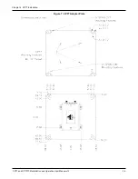
CPT7 Adapter Plate (01020112)
This plate mounts on the CPT7 and provides SPAN-CPT and SPAN-IGM compatible mounting holes. See
Secure the CPT7 Using the Adapter Plate
2.4 CPT7 Cables
To prevent damage to both the receiver and the cables, each connector can be inserted in only one way. Also,
the IO1 and IO2 connectors are keyed so that the cable can only be inserted in the connector for which it is
intended.

