136
OEM6 Family Installation and Operation User Manual Rev 7
Table 28: Ethernet Transformer Characteristics
Table 29: Bill of Materials (critical components)
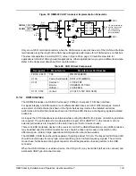
The OEM628 Ethernet LED control lines must be buffered. The buffer structure in the figure below shows
a sample LED drive circuit. Do not use the Ethernet bias 3.3 V (P1502, pins 3 and 6) to drive the LEDs.
The Ethernet bias should only be routed to the Ethernet magnetics.
Figure 68: Ethernet LED Buffer Schematic
Parameter
Value
Test Condition
Turns ratio
1 CT : 1 CT
Open-CCT inductance (minimum)
350 uH
100 mV, 100 kHz, 8 mA
Leakage inductance (maximum)
0.4 uH
1 MHz (minimum)
Inter-winding capacitance (minimum)
12 pF
DC resistance (maximum)
0.9
Ω
Insertion loss (maximum)
1.0 dB
0 MHz – 65 MHz
HIPOT (minimum)
1500 Vrms
Designator
Manufacturer
Manufacturer Part Number
FFB100, FB101, FB102 TDK
MMZ1005B800C
U100
Halo
TG110-E050N5RL
U101, U102
Semtech
Bourns
OnSemi
LC03-6.TBT
CDNBS08-PLC03-6
LC03-6R2G
C105, C106, C107
AVX
1206GC102KAT1A
3V3
R100
10K-1%
R101
10K-1%
R102
220
D100
Green
Q100
MMBT2907A
D
CHN_ETH_LED_A
P1502, pin 7
Link/Act Indicator
3V3
R103
10K-1%
R104
10K-1%
R105
220
D101
Yellow
Q101
MMBT2907A
D
CHN_ETH_LED_B
P1502, pin 8
100BT Indicator


