Installation OEM6 Family Cards
Chapter 2
OEM6 Family Installation and Operation User Manual Rev 7
29
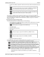
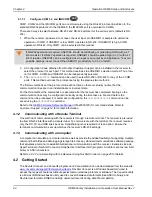
Figure 9: OEM617D Connectors and Indicators
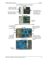
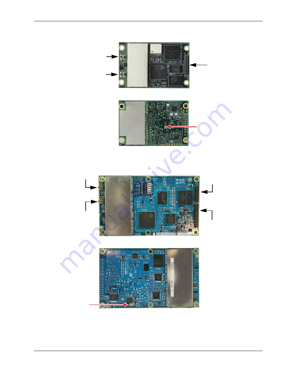
Figure 10: OEM628 Connector and Indicator Locations
BOTTOM VIEW
TOP VIEW
LED Status
Indicator
J1101 20-pin dual-row
male connector with a 2
mm straight 2 x 10
header, used for power,
data and signaling
Primary RF signal input
and LNA power output,
MMCX female connector
Secondary RF signal input
and LNA power output,
MMCX female connector
TOP VIEW
BOTTOM VIEW
P1500 24-pin dual-row
male connector with a 2
mm straight 2 x 12 header,
used for power, data and
signaling
P1502 16-pin dual-row
male connector with a 2
mm straight 2 x 8
header
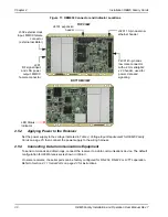
J100
RF signal input
and LNA power
output, MMCX
female connector
J101 external clock
input, MMCX female
connector
(external oscillator)
LED Status
Indicator

