30
OEM6 Family Installation and Operation User Manual Rev 7
Chapter 2
Installation OEM6 Family Cards
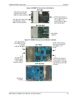
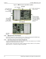
Figure 11: OEM638 Connector and Indicator Locations
2.5.2
Applying Power to the Receiver
Set the power supply to the voltage indicated in
Table 2, Voltage Input Requirement for OEM6 Family
, then connect the power supply to the wiring harness.
2.5.3
Connecting Data Communications Equipment
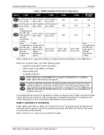
To send commands and obtain logs, connect the receiver to a data communications device. The default
configuration for OEM6 receivers is shown in
On some receivers, the serial ports can be factory configured for RS-232, RS-422 or LVTTL operation.
Refer to
Section 4.1.1 Serial Ports on page 43
for instructions.
TOP VIEW
BOTTOM VIEW
P4001 40-pin dual-
row male connector
with a 2 mm straight 2
x 20 header, used for
power, data and
signaling
J3201 10-pin dual-row
ethernet header
J201
RF signal input
and LNA power
output, MMCX
female connector
J302 external clock
input, MMCX female
connector
(external oscillator)
LED Status
Indicator
J4101 expansion
header

