OEM628 Technical Specifications
Appendix D
OEM6 Family Installation and Operation User Manual Rev 12
159
D.1.5
Ethernet Port
The OEM628 provides a 10/100 Ethernet port with auto-negotiation. The Ethernet interface is disabled by
default and must be configured. See the
OEM6 Family Firmware Reference Manual
(OM-20000129) for
instructions on Ethernet device configuration. The PHY layer is based on the Micrel KSZ8851 Ethernet
controller.
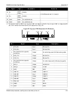
PHY terminations are provided on the OEM628 card and a 3.3 V output is presented to bias the Ethernet
magnetics. The 3.3 V power supplied by the OEM628 card is not to be used for any purposes other than
biasing the Ethernet magnetics.
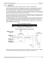
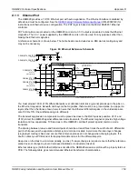
A reference schematic is shown below. The ferrite beads are included as an EMI de-risk contingency and
may not be necessary.
Figure 84: Ethernet Reference Schematic
You must provide 100
Ω
±10% differential pairs over unbroken reference (ground) planes up to the pins on
the Ethernet magnetics. Beneath and beyond the magnetics, there must be no ground plane (no copper on
layers other than the traces shown here). Ensure that the Ethernet differential pairs in the voided area are
also 100
Ω
±10% (the widths/spacing are different).
The transient suppression components must be placed as close to the RJ45 jack as possible. U101 and
U102 protect the OEM628 against differential mode transients. The Ethernet magnetics provide high voltage
isolation and low capacitance TVS devices on the OEM628 card itself protect against common mode
transients.
The spacing between receive and transmit pairs should be at least three times the width of each differential
pair (both traces plus the separation distance) to minimize crosstalk. Avoid more than two layer changes
(single layer routing is best) and ensure that reference planes do not change when changing layers. If in
doubt, contact your PCB vendor for appropriate dimensions for the differential pairs.
Keep vias on the lines to a minimum (ideally, no vias). If a layer change is required, ensure that the reference
plane does not change to prevent increased radiated or conducted emissions.
Ethernet cable type (Cat5/Cat5e/Cat6) does not affect the OEM628 emissions profile with a properly laid out
PCB. The following table gives recommended Ethernet transformer characteristics.
R101
49.9-1%
R
103
52.3-1%
R
102
52.3-1%
R100
49.9-1%
Transient Suppression
(near RJ45 connector)
C106 1000 pF
1206 2kV
1206 2kV
SHELL1 SHELL2
MODULAR JACK
C105 1000pF
1206 2kV
ETH_TD-
ETH_RD-
U100
HALO TG110-E050N5RL
C100
0.1µF
C101
0.1µF
C102
0.01µF
C103
0.1µF
C104
0.1µF
C108
1000pF
1206 2kV
All planes voided beneath these traces!
C107
1000pF
D
D
D
D
D
D
D
D
FB100
FB101
DIFF PAIR (100 ohm)
DIFF PAIR (100 ohm)
DIFF PAIR
(100 ohm)
DIFF PAIR
(100 ohm)
DIFF PAIR
(100 ohm)
DIFF PAIR
(100 ohm)
FB102
ETH_3V3
ETH_3V3
ETH_3V3
P1502, pin 3
OEM628_ETH_CENTRETAP
P1502, pin 6
OEM628_ETH_CENTRETAP
P1502, pin 5
OEM628_ETH_TD-
P1502, pin 4
OEM628
P1502, pin 1
OEM628_ETH_RD-
P1502, pin 2
OEM628
U101
PLC03-6
IO1
GND1
GND2
IO2
IO4
GND4
GND3
IO3
1
2
3
4
8
7
6
5
1
2
3
4
5
6
7
8
TX-
TX+
RX-
NC1
NC2
RX+
NC3
NC4
9
10
11
T1_N
T1_CT
T1_P
U102
PLC03-6
IO1
GND1
GND2
IO2
IO4
GND4
GND3
IO3
1
2
3
4
8
7
6
5
14
15
16
T2_N
T2_CT
T2_P
12
13
5
4
NC1
NC2
T1_PS1
T1_CTS
T1_PS2
T2_PS1
T2_CTS
T2_PS2
NC3
NC4
8
7
6
3
2
1

