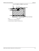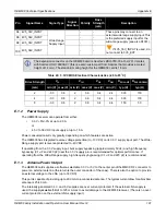
OEM638 Technical Specifications
Appendix E
OEM6 Family Installation and Operation User Manual Rev 12
172
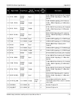
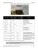
14 CTS1 / RXD1-
RS232 /
RS422
Input
-
CTS1: RS232 Flow Control (±25 V tolerant)
RXD1-: RS422 Signaling (2 V differential
typical)
15 TXD1 / TXD1+
RS232 /
RS422
Output
-
TXD1: RS232 Signaling (±25 V tolerant)
TXD1+: RS422 Signaling (2 V differential
typical)
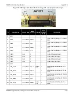
16 RTS1 / TXD1-
RS232 /
RS422
Output
-
RTS1: RS232 Flow Control (±25 V tolerant)
TXD1-: RS422 Signaling (2 V differential
typical)
17 RXD1 / RXD1+
RS232 /
RS422
Input
-
RXD1: RS232 Signaling (±25 V tolerant)
RXD1+: RS422 Signaling (2 V differential
typical)
18 CTS3 3.3V
CMOS Input
-
COM3 UART Signaling (3.3 V CMOS logic)
19 TXD3
3.3V CMOS Output
2
COM3 UART Signaling (3.3 V CMOS logic)
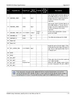
20 DCD2
RS232
Input
-
DCD2: RS232 Flow Control (±25 V
tolerant)
21 RXD3
3.3V CMOS Input
-
COM3 UART Signaling (3.3 V CMOS logic)
22 RTS3
3.3V CMOS Output
2
COM3 UART Signaling (3.3 V CMOS logic)
23 DTR2
RS232
Output
-
DTR2: RS232 Flow Control (±25 V tolerant)
24 CTS2 / RXD2-
RS232 /
RS422
Input
-
CTS2: RS232 Flow Control (±25 V tolerant)
RXD2-: RS422 Signaling (2 V differential
typical)
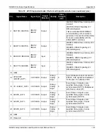
25 TXD2 / TXD2+
RS232 /
RS422
Output
-
TXD2: RS232 Flow Control (±15 V tolerant)
TXD2+: RS422 Signaling (2 V differential
typical)
26 RTS2 / TXD2-
RS232 /
RS422
Output
-
RTS2: RS232 Flow Control (±25 V tolerant)
RXD2-: RS422 Signaling (2 V differential
typical)
27 RXD2 / RXD2+
RS232 /
RS422
Input
-
RXD2: RS232 Signaling (±25 V tolerant)
RXD2-: RS422 Signaling (2 V differential
typical)
28 STATUS_GRN
3.3V CMOS Output
Active
High
2
Green Status LED Control. Used to
indicate the state of the receiver or provide
error codes.
29 USERIO0
3.3V CMOS IO
2
General Purpose IO.
30 USERIO1
a
3.3V CMOS IO
2
General Purpose IO.
Pin
Signal Name
Signal Type
Signal
Direction
Polarity
Drive
Strength
(mA)
Description

