OEM638 Technical Specifications
Appendix E
OEM6 Family Installation and Operation User Manual Rev 12
174
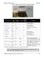
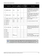
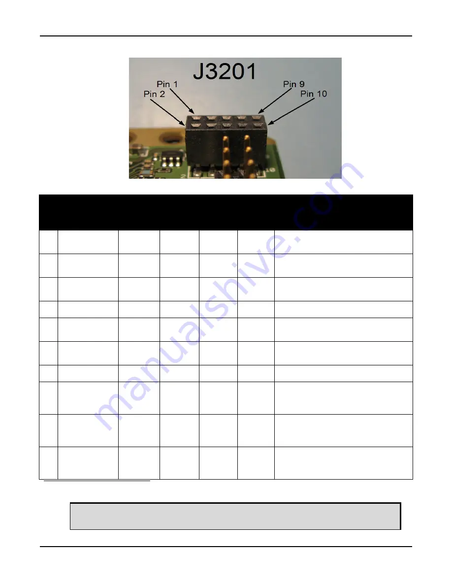
Figure 89: J3201 Ethernet Header Pin-Out and Signal Description
Pin
Signal Name
Signal
Type
Signal
Direction
Polarity
Drive
Strength
(mA)
Description
1
Analog
IO
-
Ethernet Transmit
(100
Ω
differential pair)
2
ETH_TX-
Analog
IO
-
Ethernet Transmit
(100
Ω
differential pair)
3
ETH_BIAS
PWR
Output
-
DC Bias source for the Ethernet
magnetics
4
GND
a
GND
-
-
5
Analog
IO
-
Ethernet Receive
(100
Ω
differential pair)
6
ETH_RX-
Analog
IO
-
Ethernet Receive
(100
Ω
differential pair)
7
GND
a
GND
-
-
8
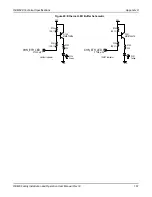
ETH_LED_ACT
3.3V Open
Drain
Sink
Active
Low
8
Ethernet “Activity” LED indicator.
Connect to LED supplied from 3.3 V. Do
not use the ETH_BIAS to supply the LED.
9
ETH_LED_SPD
3.3V Open
Drain
Sink
Active
Low
8
Ethernet “Speed” LED indicator. Connect
to LED supplied from 3.3 V. Do not use
the ETH_BIAS to supply the LED.
10 ETH_LED_LNK
3.3V Open
Drain
Sink
Active
Low
8
Ethernet “Link” LED indicator. Connect to
LED supplied from 3.3 V. Do not use the
ETH_BIAS to supply the LED.
a. Connect to the chassis ground through a bead or capacitor for best performance.
This connector mates with
Samtec TW-05-03-G-D-240-090
(or similar). The standard
mating height for the OEM638 card is 14 mm.


