Installation OEM6 Family Cards
Chapter 2
OEM6 Family Installation and Operation User Manual Rev 12
38
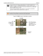
Figure 14: OEM638 Connector and Indicator Locations
2.5.2
Applying Power to the Receiver
Set the power supply to the voltage indicated in
Table 3, Voltage Input Requirement for OEM6 Family Cards
on page 31, then connect the power supply to the wiring harness.
2.5.3
Connecting Data Communications Equipment
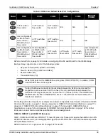
To send commands and obtain logs, connect the receiver to a data communications device. The default
configuration for OEM6 receivers is shown in
Table 4, OEM6 Card Default Serial Port Configurations
On some receivers, the serial ports can be user configured for RS-232, RS-422 or LVTTL operation. Refer to
on page 52 for instructions.
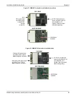
TOP VIEW
BOTTOM VIEW
P4001 40-pin dual-
row male connector
with a 2 mm straight 2
x 20 header, used for
power, data and
signaling
J3201 10-pin dual-row
Ethernet header
J201
RF signal input
and LNA power
output, MMCX
female connector
J302 external clock
input, MMCX female
connector
(external oscillator)
LED Status
Indicator
J4101 expansion
header


