Operation OEM6 Cards and Enclosures
Chapter 4
OEM6 Family Installation and Operation User Manual Rev 12
56
Figure 23: Basic Differential Setup
For information on positioning errors and the application of corrections for them, refer to the application note
APN-051 Positioning Modes of Operation
. To receive corrections with
a base/rover setup, a data link between the base station and the rover station is required. The base and rover
stations can both be NovAtel receivers, however NovAtel receivers will work with some other brands. Contact
Customer Support for further details (refer to
on page 18 for details).
The data link should support a rate of at least 19200 bits per second, but a rate of 115200 bits per second,
with less than 4.0 s latency, is recommended. Unlike the base/rover concept, SBAS and L-Band corrections
can be applied directly to a single receiver.
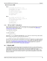
Rover Setup
Base Setup
1
Mount and connect a GNSS antenna
1
Mount and connect a GNSS antenna
2
Connect a power supply (user supplied)
2
Connect a power supply (user supplied)
3
Connect a radio device to COM2 (user supplied) 3
Connect a radio device to COM2 (user supplied)
4
Connect a storage device to COM1 (user
supplied)
4
Connect a computer to COM1 for setup and
monitoring (user supplied)
ROVER
BASE
GNSS
Antenna
GNSS
Antenna
Radio}
COM2
Power
Computer
(USB shown)
Base
Enclosure
Radio
COM2
Rover
Enclosure
Power
COM1
Data Storage


