58
SPAN-SE User Manual Rev 1
Chapter 3
SPAN-SE Operation
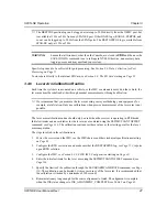
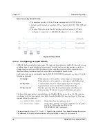
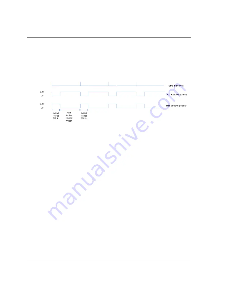
Rules Governing Period Widths:
• The minimum period is 1000 ns. The maximum period is 999 999 000 ns.
• Periods must be entered as a multiple of 25 ns, that is 1000, 1025, 1050, 1075 and
so on.
• The sum of the active and not-active periods must be a factor of 1 s. That is:
K ( not-active) = 1 000 000 000, where K = 1, 2, 3, ..., 500 000
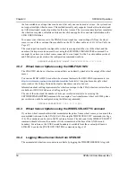
Figure 12: Event Out
3.10.2
Configuring an Input Strobe
SPAN-SE has four available input strobes. The input strobes apply an accurate GPS time to the rising,
or falling, edge of an input pulse called an event. For each event, an accurate position, velocity or
attitude solution is also available. Each input strobe is usually associated with a separate device,
therefore different solution output lever arm offsets can be applied to each strobe.
Each input strobe can be configured using the EVENTINCONTROL command, see
, for the
following parameters:
1. Polarity:
When polarity is set to positive, events trigger on the rising edge.
When polarity is set to negative, events trigger on the falling edge.
2. Time Bias:
A constant time bias in ns can be applied to each event pulse.
Typically this is used to account for a transmission delay.
3. Time Guard:
The time guard specifies the minimum number of milliseconds
between pulses. This is used to coarsely filter the input pulses.
The time of the input pulses is available from the MARK
x
TIME logs, see
. The solution
synchronous with the event pulses is available from the MARK
x
PVA logs, see
. The logs
required for input strobes are:
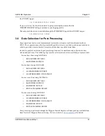
LOG MARK1TIMEB ONNEW
Output time for every pulse received.
LOG MARK1PVAB ONNEW
Output time, position, velocity and attitude for every pulse
received at the location specified by the
SETMARK1OFFSET command.
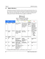
The input signal levels are 3.75 V to -0.3 V. Signal voltages outside these bounds damage the receiver.
The minimum detectable pulse duration must be greater than or equal to 1 microsecond.
*


