background image

102

SPAN-SE User Manual Rev 1

Appendix B

Commands

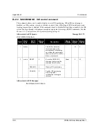
B.4.7

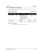
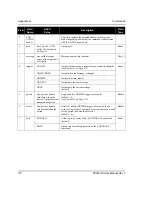
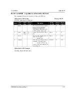
EVENTOUTCONTROL

Control PPS signal properties

This command controls up to three Event-Out output triggers (PPS signal properties). See also 

Section 

3.10, Synchronizing External Equipment 

starting on 

Page 57

.

The 

EVENTOUTCONTROL MARK1 ENABLE POSITIVE 10000000 240000000


command will generate a 4 Hz signal. The signal is held high for 10 ms during each cycle and the 

leading edge of the high signal is aligned to the 1PPS.

Abbreviated ASCII Syntax:

Message ID: 613

EVENTOUTCONTROL mark switch [polarity] [active period] [non-active period

]

Abbreviated ASCII Example:

EVENTOUTCONTROL MARK3 ENABLE

Field

Field
Type

ASCII
Value

Binary

Value

Description

Binary

Format

Binary

Bytes

Binary

Offset

1

header

-

-

This field contains the 

command name or the 

message header depending on 

whether the command is 

abbreviated ASCII, ASCII or 

binary, respectively.

-

H

0

2

mark

MARK1

0

Choose which Event-Out 

mark to use

Enum

4

H

MARK2

1

MARK3

2

3

switch

DISABLE

0

Disables Event output

Enum

4

H+4

ENABLE

1

4

polarity NEGATIVE 0

Negative polarity (default)

Enum

4

H+8

POSITIVE

1

Positive polarity

5

active 

period

Active period of the Event Out 

signal in nanoseconds:

default 

= 500 000 000

minimum =  1000

maximum  = 999 999 000

Ulong

4

H+12

6

not-

active 

period

Not-active period of the Event 

Out signal in nanoseconds:

default 

= 500 000 000

minimum =  1000

maximum  = 999 999 000

Ulong

4

H+16

Summary of Contents for SPAN-SE

Page 1: ...OM 20000124 Rev 1 USER MANUAL SPAN SE...

Page 2: ...c or mechanical including photocopying and recording for any purpose without the express written permission of a duly authorized representative of NovAtel Inc The information contained within this man...

Page 3: ...rame 35 3 1 4 The Vehicle Frame 35 3 2 Communicating with the SPAN System 36 3 2 1 INS Window in CDU 38 3 3 Software Configuration 39 3 3 1 GNSS Configuration 39 3 3 2 SPAN IMU Configuration 40 3 4 Re...

Page 4: ...2 Inertial Measurement Units IMUs 69 A 2 1 LN 200 IMU 69 A 2 2 iIMU FSAS 74 A 2 3 HG1700 IMU 83 B Commands 86 B 1 Command Formats 86 B 2 Using a Command as a Log 86 B 3 DOS Commands 87 B 3 1 DIR Show...

Page 5: ...muth and standard deviation 141 B 4 33 SETINSOFFSET Set INS offset 143 B 4 34 SETMARK1OFFSET SETMARK2OFFSET SETMARK3OFFSET SETMARK4OFFSET Set Mark offset 144 B 4 35 SETWHEELPARAMETERS Set wheel parame...

Page 6: ...E INS Update 218 C 4 31 INSVEL INS Velocity 220 C 4 32 INSVELS Short INS Velocity 221 C 4 33 LBANDINFO L band Configuration Information 222 C 4 34 LBANDSTAT L band Status Information 224 C 4 35 LOGLIS...

Page 7: ...0 E 4 Re Assemble the SPAN IMU Enclosure 281 F LN 200 IMU Installation 282 F 1 Disassemble the SPAN IMU Enclosure 283 F 2 Install the LN 200 Sensor Unit 284 F 3 Make the Electrical Connections 285 F 4...

Page 8: ...22 iIMU FSAS Top Bottom Dimensions 74 23 iIMU FSAS Enclosure Side Dimensions 75 24 iIMU FSAS Centre of Navigation 76 25 iIMU Interface Cable Connections with a SPAN SE 77 26 FSAS SPAN SE Y Adapter Cab...

Page 9: ...s 98 23 FRESET Target 104 24 Serial Port Interface Modes 106 25 NMEA Talkers 118 26 DGPS Type 120 27 Dynamics Mode 124 28 System Types 129 29 Full Mapping Definitions 135 30 IMU Type 138 31 SETWHEELPA...

Page 10: ...ord Format RANGECMP only 244 60 HG1700 IMU Status 248 61 LN 200 IMU Status 249 62 iIMU FSAS Status 250 63 HG1700 IMU Status Example 251 64 Raw IMU Scale Factors 253 65 SPAN Receiver Error 257 66 SPAN...

Page 11: ...or any other words or combinations of words proprietary to NovAtel in connection with this Agreement without the prior written consent of NovAtel 3 Patent Infringement NovAtel shall not be liable to...

Page 12: ...bution or otherwise howsoever to the Licensee and the Licensee will indemnify and hold NovAtel harmless against all or any loss dam age actions costs claims demands and other liabilities or any kind w...

Page 13: ...d insure Products in transit and charge Purchaser accordingly NovAtel shall not be responsible for any failure to perform due to unforeseen circumstances or causes beyond its ability to reasonably con...

Page 14: ...FITNESS FOR A PARTICULAR PURPOSE NOVATEL SHALL IN NO EVENT BE LIABLE FOR SPECIAL INDIRECT INCIDENTAL OR CONSEQUENTIAL DAMAGES OF ANY KIND OR NATURE DUE TO ANY CAUSE Purchaser s exclusive remedy for a...

Page 15: ...ny breach of the Order or of statutory duty or by reason of tort including but not limited to negligence for any loss of profit loss of use loss of production loss of contracts or for any financing co...

Page 16: ...its manufacturer and not to NovAtel 1 Litton Northrop Grumman Litton Systems Inc Navigation Systems Division NSD 21240 Burbank Blvd Woodland Hills CA 91367 iMar iMAR GmbH Im Reihersbruch 3 D 66386 St...

Page 17: ...damage THE FOREGOING WARRANTIES DO NOT EXTEND TO I NONCONFORMITIES DEFECTS OR ERRORS IN THE PRODUCTS DUE TO ACCIDENT ABUSE MISUSE OR NEGLIGENT USE OF THE PRODUCTS OR USE IN OTHER THAN A NORMAL AND CUS...

Page 18: ...ntact NovAtel Inc directly using one of the following methods Call the NovAtel GNSS Hotline at 1 800 NOVATEL North America or 403 295 4900 international Fax 403 295 4901 E mail support novatel ca Webs...

Page 19: ...s device incorporates circuitry to absorb most static discharges However severe static shock may cause inaccurate operation of the unit Use anti static precautions where possible 2 This device is a pr...

Page 20: ...ple modular system This allows the IMU mounting at the most suitable location while the GNSS receiver is mounted where it is most convenient SPAN Technology provides a robust GNSS and Inertial solutio...

Page 21: ...the installation requirements and considerations for the different parts of the SPAN system To run the SPAN system software your personal computer must meet or exceed this minimum configuration Micro...

Page 22: ...d GNSS INS solution has the advantage of the absolute accuracy available from GNSS and the continuity of INS through traditionally difficult GNSS conditions SPAN SE is the solution engine of NovAtel s...

Page 23: ...rial link A NovAtel GNSS antenna must also be connected to the receiver to track GNSS signals Once the IMU enclosure GNSS antenna and appropriate power supplies are attached and a few simple configura...

Page 24: ...lution is impossible Provide faster signal reacquisition and RTK solution resolution over stand alone GNSS because of the tightly integrated GNSS and INS filters Output high rate up to 100 or 200 Hz d...

Page 25: ...any time anywhere without any mechanical procedures whatsoever For example a model with L1 L2 only capabilities can be upgraded to a model with L1 L2 RT 2 in only a few minutes in your office instead...

Page 26: ...tial operation a communication link between the base and rover s is necessary This can be a null modem cable or a radio link Figure 3 on Page 27 shows a basic setup plus a radio link on the base and t...

Page 27: ...lied radio device to the connector labelled OEMV3 on the SPAN SE I O green cable 6 User supplied base station ProPak V3 receiver 7 User supplied PC laptop for setting up and monitoring to COM1 on the...

Page 28: ...ed for logging of high rate data Data storage is via a Secure Digital SD memory card that you access in the front of the SPAN SE See also Section 3 8 The SD Card starting on Page 53 Figure 4 SD Memory...

Page 29: ...tions that follow show the connections on the back of a SPAN SE receiver 2 2 SPAN SE Hardware Installation 2 2 1 Mount Antenna For the best possible positioning precision and accuracy as well as to mi...

Page 30: ...n the GNSS positions being used For example a 10 cm error in recording the antenna offset will result in at least a 10 cm error in the output Millimeter accuracy is preferred 2 The offset from the IMU...

Page 31: ...appropriate DC power supply The receiver has an internal power module that does the following filters and regulates the supply voltage protects against over voltage over current and high temperature...

Page 32: ...stem when it has been automatically shut down and to manually power down the system The state of the button depends on the amount of time the power button is depressed Table 4 Power Button States Figu...

Page 33: ...starting on Page 57 See Section A 1 1 3 I O 2 Yellow Cable NovAtel part number 01018133 on Page 67 for its bare wire pin outs The jacket insulation is cut away slightly from the end but the insulatio...

Page 34: ...novatel com for details 3 1 Definition of Reference Frames Within SPAN The reference frames that are most frequently used throughout this manual are the following The Local Level Frame The SPAN Comput...

Page 35: ...losure pointing up the IMU enclosure frame is the same as the SPAN computation frame This origin of this frame is not the enclosure center but the Center of Navigation sensor center Figure 8 The Enclo...

Page 36: ...The Help file is accessed by choosing Help from the main menu in CDU Start CDU on your PC to enable communication 1 Launch CDU from the Start menu folder specified during the installation process The...

Page 37: ...handshaking checkbox 8 Select OK to save the new device settings 9 Select the new configuration from the Available device configs area of the Open dialog 10 Select the Open button to open receiver com...

Page 38: ...he Position Velocity and Attitude roll pitch and azimuth sections display data from the INSPVA log along with standard deviations calculated from the INSCOV log Information in the ZUPT Zero Velocity U...

Page 39: ...ration The GNSS positioning mode of operation can also be configured using the position mode wizard in NovAtel s Control and Display Unit CDU software utility See CDU s Help and its wizard screens for...

Page 40: ...phase centre and the IMU center of navigation must remain con stant and be known accurately m The X pitch Y roll and Z azimuth directions are clearly marked on the IMU enclosure The SETIMUTOANTOFFSET...

Page 41: ...Select Tools SPAN Alignment Wizard from the main menu of CDU This wizard takes you through the steps to complete a coarse or fast alignment select the type of IMU and configure the receiver port conn...

Page 42: ...E User Manual Rev 1 Chapter 3 SPAN SE Operation You need only run the Calibration Wizard if you need to calibrate the lever arm or vehicle to frame angular offsets It is not required for the SPAN filt...

Page 43: ...er logs to save throughput Status of the inertial solution can be monitored using the inertial status field in the INS logs Table 5 below Table 5 Inertial Solution Status Binary ASCII Description 0 IN...

Page 44: ...4 3 System Start Up and Alignment Techniques WARNING If logging to a PC ensure the Control Panel s Power Settings on your PC are not set to go into Hibernate or Standby modes Data will be lost if one...

Page 45: ...use the vehicle cannot remain stationary for the length of time required an alternate alignment routine is available The kinematic or moving alignment is performed by estimating the attitude from the...

Page 46: ...e SPAN models system errors by using a Kalman filter The GNSS solution phase observations and automatic zero velocity updates ZUPTs provide updates to the Kalman filter When a wheel sensor is connecte...

Page 47: ...ment for example a total station Only use calibrations when precise measurement of the lever arm is not possible The lever arm calibration routine should only be used when the receiver is operating in...

Page 48: ...e provides a more accurate estimation of the values As with the lever arm calibration the vehicle to SPAN frame angular offset calibration requires RTK GNSS The steps for the calibration routine are 1...

Page 49: ...ATION command is enabled see Page 90 3 5 SPAN Wheel Sensor Configuration The SPAN SE receiver supports various wheel sensor inputs A wheel sensor can be used to measure the distance travelled by count...

Page 50: ...put of the wheel sensor You can use iMAR s iMWS or another wheel sensor that meets the iIMU FSAS requirements see http www imar navigation de englishside imar htm for details An optical encoder style...

Page 51: ...te solution than is possible in real time In order to generate a solution in post processing data must be simultaneously collected at a base station and each rover The following logs must be collected...

Page 52: ...ng same as above but a file is open Card busy either formatting or mounting Card in but has 1 space remaining and logging stops automatically Flashing SD card error that can occur at any time regardle...

Page 53: ...ry Card on Page 28 The SD Card access door is shown closed in Figure 11 below Move the arrow latch to the left to open the access door To remove the SD Card unlock the access door When the door is ope...

Page 54: ...s to an automatically named file in the root directory of the SD Card see Section 3 9 5 Log a Pre Defined List of Logs on Page 55 Otherwise continue to Step 3 3 Select the location on the disk to stor...

Page 55: ...rking directory Press the button a second time to stop the logging and close the file Press the button a third time to re start the logging to a new file and so on The LOGFILE command lets you start a...

Page 56: ...logs RAWIMUSB data 3 9 6 Auto Logging on Start Up After configuring log output using the LOG commands configure the receiver to log the log profile on start up every time by issuing these two command...

Page 57: ...de can be generated and output synchronously with each input pulse 3 10 1 Configuring a Synchronous Output Pulse The EVENTOUTCONTROL command see Page 102 is used to configure an output strobe There ar...

Page 58: ...command see Page 101 for the following parameters 1 Polarity When polarity is set to positive events trigger on the rising edge When polarity is set to negative events trigger on the falling edge 2 Ti...

Page 59: ...l TCP and User Datagram Protocol UDP traffic but not simultaneously SPAN SE uses a static IP address Dynamic Host Configuration Protocol DHCP is a protocol for automating the configuration of computer...

Page 60: ...is configured in TCP mode only one connection to the receiver is allowed at a time Data automatically streams to the IP address that connects to the port Because UDP is a connectionless protocol mult...

Page 61: ...stallation and Operation User Manual A 1 1 SPAN SE Receiver INPUT OUTPUT CONNECTORS Antenna Input 1 and 2 TNC female jack 50 nominal impedance 5 V DC 100 mA max output from SPAN SE to antenna LNA Powe...

Page 62: ...TAL Tested to these standards IEC 60529 IPX7 Waterproof IEC 60529 IPX6 Dust IEC 68 2 27 60 g Shock non operating RTCA D0 160D curve C Vibration random IEC 68 2 6 Vibration sinusoidal FCC Part 15 Class...

Page 63: ...anual Rev 1 63 DIMENSIONS a a All dimensions are in millimeters please use the Unit Conversion section of GNSS A Reference Guide available from our website at www novatel com for conversion to imperia...

Page 64: ...C while operating in the field Input is provided through the bare wire power outlets The exposed wires red and orange for positive brown and black for negative can then be tied to a supply capable of...

Page 65: ...M3 COM4 both used for command input and data output a direct connection to the internal OEMV 3 COM1 used for RTK correction input and a direct connection to the internal OEMV 2 COM1 There is also an e...

Page 66: ...L1 Bare Wire BLUE 22 CAN H2 Bare Wire RED 10 CAN L2 Bare Wire BROWN 29 GND Bare Wire GREEN 30 GND Bare Wire WHITE 17 RXD3 COM3 3 16 TXD3 COM3 2 23 GND COM3 5 15 RTS3 COM3 8 1 CTS3 COM3 7 25 RXD4 COM4...

Page 67: ...with bare cables as shown in the figure below See Table 9 I O 2 Yellow Cable Connector Pin Outs on Page 68 This cable is RoHS compliant Reference Description P10 ODU 30 pin P1 P2 P7 DB 9 Figure 15 SP...

Page 68: ...VENT OUT 3 Detail B Bare Wire RED 27 GND Detail B Bare Wire GREEN 6 EVENT IN 1 Detail A Bare Wire BLACK 5 EVENT IN 2 Detail A Bare Wire BLUE 20 EVENT IN 3 Detail A Bare Wire RED 19 EVENT IN 4 Detail A...

Page 69: ...nclosure Size 135 mm x 153 mm x 130 mm 5 315 x 6 024 x 5 118 IMU Size 89 mm D x 85 mm H 3 504 D x 3 346 H IMU Weight 3 kg 6 6 lb MECHANICAL DRAWINGS Figure 16 LN 200 IMU Enclosure Top Bottom Dimension...

Page 70: ...re Side Dimensions 13 Pin 3 Pin Scale 0 800 Note The Center of label are for the internal IMU and are enclosure center The IMU Enclosure Center Navigation offsets shown on the LN 200 different than fo...

Page 71: ...5 Figures 18 and 19 below The IMU interface cable supplied enables input and output between the IMU and the receiver Figure 18 LN 200 Interface Cable Figure 19 IMU Interface Cable Pin Out ProPak V3 De...

Page 72: ...d Figure 21 the wiring diagram of the 12V adapter The output of the power adapter uses a 3 pin Deutsch socket Deutsch part number 59064 09 98SN This cable plugs directly into the 3 pin port on the fro...

Page 73: ...CAL IMU Power Consumption 16 W max IMU Input Voltage 12 to 28 V DC Receiver Power Consumption ProPak V3 2 8 W typical System Power Consumption ProPak V3 14 8 W typical Data Connector on Enclosure 13 p...

Page 74: ...Table 11 iIMU FSAS Specifications PHYSICAL IMU Size 128 mm x 128 mm x 104 mm 5 04 x 5 04 x 4 09 IMU Weight 2 1 kg 4 63 lb MECHANICAL DRAWINGS aA Figure 22 iIMU FSAS Top Bottom Dimensions a See Figure...

Page 75: ...Technical Specifications Appendix A SPAN SE User Manual Rev 1 75 Figure 23 iIMU FSAS Enclosure Side Dimensions...

Page 76: ...76 SPAN SE User Manual Rev 1 Appendix A Technical Specifications Figure 24 iIMU FSAS Centre of Navigation...

Page 77: ...Figure 25 below shows the iIMU interface cable connections when used with a SPAN SE receiver while the rest ofthe SPAN SE connections are shown in Figure 3 on Page 27 Figure 25 iIMU Interface Cable C...

Page 78: ...signal LVTTL to VARF 8 Reserved 9 DAS_ GND 9 Shielded ground reference for data acquisition control signals 10 Reserved 11 DON 8 Twisted pair serial data output signal RS 422 12 DO 2 Twisted pair ser...

Page 79: ...iIMU FSAS system iMWS V2 Magnetic Wheel Sensor from iMAR A magnetic strip and detector are installed inside the wheel The signal then goes through a box that translates the magnetic readings into puls...

Page 80: ...elow Connect the female DB9 connector to the male ODO end of the iIMU FSAS interface cable The iMAR iMWS V2 sensor is on the inside of the wheel so that all you can see in the vehicle is the grey sign...

Page 81: ...and Pin 1 is wired to a black banana plug Power return so the WPT needs power to operate 10 to 30 V Solder the shield on the WPT cable to the female DB9 housing b This modification is for the Corrsys...

Page 82: ...tional Accelerometer Linearity Accelerometer Scale Factor 400 ppm Accelerometer Bias 1 0 mg ELECTRICAL IMU Power Consumption 16 W max IMU Input Voltage 10 to 34 V DC Receiver Power Consumption ProPak...

Page 83: ...x 100 mm 7 6 x 6 6 x 3 9 IMU Size 160 mm x 160 mm x 100 mm 6 3 x 6 3 x 3 9 IMU Weight 3 4 kg 7 49 lb MECHANICAL DRAWINGS Figure 30 HG1700 Top Bottom Dimensions Note The Center of for the internal IMU...

Page 84: ...gure 31 HG1700 Enclosure Side Dimensions Scale 0 600 Note The Center of for the internal IMU IMU Enclosure Center Navigation shown on the HG1700 label enclosure s center measurements are labelled as i...

Page 85: ...1 0 mg IMU H62 Gyro Input Range 1000 degrees s Gyro Rate Bias 5 0 degrees hr Gyro Rate Scale Factor 150 ppm Angular Random Walk 0 5 degrees rt hr Accelerometer Range 50 g Accelerometer Linearity 500...

Page 86: ...SB ONTIME 1 CR ASCII Example LOGA COM2 0 66 0 UNKNOWN 0 15 917 004c0000 5255 32858 COM1 BESTPOSB ONTIME 1 000000 0 000000 NOHOLD F95592DD CR Binary Example AA44121C 01000240 20000000 1D1D0000 29160000...

Page 87: ...OS commands for accessing the SD Card DOS commands that produce output logs do not conform to traditional NovAtel command log formats The resulting logs are output as simple ASCII as with normal DOS c...

Page 88: ...er Values COM Port Enum see Table 18 on Page 95 THISPORT default Mass Storage Device Enum see Table 16 on Page 87 SD default Parameter Values Mass Storage Device Enum see Table 16 on Page 87 SD defaul...

Page 89: ...ted and no log file open for writing Attempting to use an FTP command when the card is not idle will result in this error 425 SD Card not ready B 4 SPAN SE Command Reference For convenience some commo...

Page 90: ...PLYVEHICLEBODYROTATION is disabled by default Abbreviated ASCII Syntax Message ID 1071 APPLYVEHICLEBODYROTATION switch Abbreviated ASCII Example APPLYVEHICLEBODYROTATION ENABLE Field Field Type ASCII...

Page 91: ...Hz 3 OmniSTAR has changed channels frequencies on the AMSC Satellite that broadcasts OmniSTAR corrections for North America NovAtel receivers do not need a firmware change To change frequencies conne...

Page 92: ...list is stored in NVM for subsequent auto assignments Lists are considered valid for 6 months and are constantly updated while an OmniSTAR signal is tracking If the receiver has a valid satellite list...

Page 93: ...om chart html For example Eastern US Coverage is Northern Canada to southern Mexico 1557845 or 1557845000 Field Field Type ASCII Value Binary Value Description Binary Format Binary Bytes Binary Offset...

Page 94: ...king is enabled then unexpected results may occur 2 Watch for situations where the COM ports of two receivers are connected together and the baud rates do not match Data transmitted through a port ope...

Page 95: ...iption 1 COM1 COM P ort 1 2 COM2 COM P ort 2 3 COM3 COM P ort 3 7 FILE SD Card 13 USB1 USB Device 19 COM4 COM Port 4 20 ETH1 10 100 Ethernet Binary ASCII Description 0 N No parity default 1 E Even par...

Page 96: ...0 2400 4800 9600 19200 38400 57600 115200 or 230400 Communication baud rate bps Bauds of 460800 and 921600 are also available on COM1 of OEMV 2 based products ULong 4 H 4 4 parity See Table 19 on Page...

Page 97: ...simultaneously using this command 1 If handshaking is disabled any of these modes can be used without affecting regular RS232 communications through the selected COM port However if handshaking is ena...

Page 98: ...98 SPAN SE User Manual Rev 1 Appendix B Commands Table 22 SPAN SE COM Port Values Binary ASCII 1 COM1 2 COM2 3 COM3 6 THISPORT 7 FILE 8 ALL 13 USB1 19 COM4 20 ETH1...

Page 99: ...4 H 4 DTR 1 TX 2 4 control DEFAULT 0 Disables this command and returns the COM signal to its default state Enum 4 H 8 FORCEHIGH 1 Forces signal high FORCELOW 2 Forces signal low TOGGLE 3 Immediately t...

Page 100: ...M4 Ensure the connections are correct before issuing this command to prevent damage to the electronics Abbreviated ASCII Syntax Message ID 779 COMVOUT switch Abbreviated ASCII Example COMVOUT ON Field...

Page 101: ...d is abbreviated ASCII ASCII or binary respectively H 0 2 mark MARK1 0 Choose which Event In mark to use Enum 4 H MARK2 1 MARK3 2 MARK4 3 3 event DISABLE 0 Disables Event input Enum 4 H 4 EVENT 1 Capt...

Page 102: ...CII Example EVENTOUTCONTROL MARK3 ENABLE Field Field Type ASCII Value Binary Value Description Binary Format Binary Bytes Binary Offset 1 header This field contains the command name or the message hea...

Page 103: ...me Abbreviated ASCII Example FORMAT SD Field Field Type ASCII Value Binary Value Description Binary Format Binary Bytes Binary Offset 1 header This field contains the command name or the message heade...

Page 104: ...ge ID 20 FRESET target Abbreviated ASCII Example FRESET USER_CFG Table 23 FRESET Target Field Field Type ASCII Value Binary Value Description Binary Format Binary Bytes Binary Offset 1 header This fie...

Page 105: ...t 1 header This field contains the command name or the message headerdepending on whether the command is abbreviated ASCII ASCII or binary respectively H 0 2 card CARD1 0 Select a receiver card CARD1...

Page 106: ...ProPak V3 receiver you do not need to use CDGPS as the argument The CDGPS argument is for use with obsolete external non NovAtel CDGPS receivers These receivers use GPS C NavCanada s proprietary forma...

Page 107: ...D 1059 IFCONFIG IP mask gateway Abbreviated ASCII Example IFCONFIG 198 161 73 11 255 255 255 0 198 161 73 1 Field Field Type ASCII Value Binary Value Description Binary Format Binary Bytes Binary Offs...

Page 108: ...ESET command See also Section 3 4 1 Configuration for Alignment starting on Page 44 Abbreviated ASCII Syntax Message ID 379 INSCOMMAND action Abbreviated ASCII Example INSCOMMAND ENABLE Field Field Ty...

Page 109: ...orm a Zero Velocity Update ZUPT that is to update the receiver when the system has stopped NovAtel s SPAN Technology System does ZUPTs automatically It is not necessary to use this command under norma...

Page 110: ...177 If a SETIMUANTOFFSET command is already entered or there is a previously saved lever arm in NVM before the LEVERARMCALIBRATE is sent the calibration starts using initial values from SETIMUTOANTOFF...

Page 111: ...The example s 600 s duration is from when calibration begins and not from when you issue the command Abbreviated ASCII Example 2 LEVERARMCALIBRATE 600 0 05 Given this command the lever arm calibratio...

Page 112: ...ata If you attempt to log more than 30 logs at a time the receiver responds with an Insufficient Resources error 2 Maximum flexibility for logging data is provided to the user by these logs The user i...

Page 113: ...ogging to COM port 1 at 1 second intervals and offset by 0 5 seconds output at 0 5 1 5 2 5 seconds and so on The hold parameter is set so that logging is not disrupted by the UNLOGALL command To send...

Page 114: ...d ASCII NMEA 11 Reserved Bit 7 Response Bit 0 Original Message 1 Response Message Message type of log Char 1 H 6 5 Reserved Char 1 H 7 6 trigger 0 ONNEW Does not output current message but outputs whe...

Page 115: ...every minute you would set the period to 60 and the offset to 1 Double 8 H 20 9 hold 0 NOHOLD Allow log to be removed by the UNLOGALL command Enum 4 H 28 1 HOLD Prevent log from being removed by the d...

Page 116: ...on Page 115 Enum ONCHANGED Output when the message is changed ONTIME Output on a time interval ONNEXT Output only the next message ONCE Output only the current message default 5 period Any positive d...

Page 117: ...ue Description Binary Format Binary Bytes Binary Offset 1 header This field contains the command name or the message header depending on whether the command is abbreviated ASCII ASCII or binary respec...

Page 118: ...ALKER ID Factory Default nmeatalker gp Abbreviated ASCII Example NMEATALKER AUTO This command only affects NMEA logs that are capable of an INS position and or velocity output For example GPGSV is for...

Page 119: ...a base at a known location can monitor the errors and generate corrections for the rover to use This method is called Differential GPS and is used by surveyors to obtain millimeter accuracy Major fac...

Page 120: ...f SBAS as the pseudorange differential source SBAS is able to simultaneously track two SBAS satellites and incorporate the SBAS corrections into the position to generate differential quality position...

Page 121: ...eviated ASCII ASCII or binary respectively H 0 2 type See Table 26 on Page 120 ID Type All type s may revert to SBAS if enabled or SINGLE position types See also Table 38 Position or Velocity Type on...

Page 122: ...ional delay field is used to set the number of seconds the receiver is to wait before resetting The RESET command can be used to erase any unsaved changes to the receiver configuration Abbreviated ASC...

Page 123: ...EFAULTS command executes the following commands RTKDYNAMICS DYNAMIC RTKSVENTRIES 12 Abbreviated ASCII Syntax Message ID 97 RTKCOMMAND action Factory Default rtkcommand use_defaults Abbreviated ASCII E...

Page 124: ...ce the antenna should not move more than 1 2 cm when in static mode 2 Use the static option to decrease the time required to fix ambiguities and reduce the amount of noise in the position solution If...

Page 125: ...Contact NovAtel for details Contact information may be found on the back of this manual or you can refer to the Customer Service section in the OEMV Family Installation and Operation User Manual Abbr...

Page 126: ...essage header depending on whether the command is abbreviated ASCII ASCII or binary respectively H 0 2 type See Table 26 DGPS Type on Page 120 ID Type 1 Enum 4 H 3 ID Char 5 or ANY ID string Char 5 8...

Page 127: ...for the SPAN system to solve the vehicle SPAN body offset The solved vehicle body rotation parameters are output in the VEHICLEBODYROTATION log when the calibration is complete see Page 269 When the c...

Page 128: ...settings FIX settings port configurations and so on Its output is in the RXCONFIG log see Page 254 See also the FRESET command Page 104 WARNING If you are using this command in CDU ensure that you hav...

Page 129: ...y of knowing each other are there The testmode parameter in the example is to get around the test mode of these systems EGNOS at one time used the IGNOREZERO test mode At the time of printing ZEROTOTW...

Page 130: ...AS corrections it receives Enum 4 H ENABLE 1 Receiver uses the SBAS corrections it receives 3 system See Table 28 on Page 129 Choose the SBAS the receiver will use Enum 4 H 4 4 prn 0 Receiver uses any...

Page 131: ...GGING is ON but no logs to the FILE port have been requested no data is written to the card but a blank file is created The user can still type LOGFILE CLOSE at any time to stop logging to the file wh...

Page 132: ...TOCOL command with its one non optional parameter IMPORTANT You must manually reset the system for this setting to take effect using the RESET command or a power cycle See also the RESET command on Pa...

Page 133: ...VECONFIG command to save settings in NVM Otherwise unnecessary data logging occurs and may overload your system This orientation command serves to transform the incoming IMU signals in such a way that...

Page 134: ...viated ASCII Syntax Message ID 567 SETIMUORIENTATION switch Abbreviated ASCII Example SETIMUORIENTATION 1 Field Field Type ASCII Value Binary Value Description Binary Format Binary Bytes Binary Offset...

Page 135: ...Commands Appendix B SPAN SE User Manual Rev 1 135 Table 29 Full Mapping Definitions...

Page 136: ...d Z azimuth directions of the inertial frame are clearly marked on the IMU This command must be entered before or during the INS alignment mode not after Abbreviated ASCII Syntax Message ID 383 SETIMU...

Page 137: ...hen use the SAVECONFIG command to save settings in NVM Otherwise unnecessary data logging occurs and may overload your system Abbreviated ASCII Syntax Message ID 569 SETIMUTYPE switch Field Field Type...

Page 138: ...U_UNKNOWN Unknown IMU type default 1 IMU_HG1700_AG11 Honeywell HG1700 AG11 AG58 2 3 Reserved 4 IMU_HG1700_AG17 Honeywell HG1700 AG17 AG62 5 7 Reserved 8 IMU_LN200 Litton LN 200 200 Hz model 9 IMU_LN20...

Page 139: ...and azimuth about the z axis are with respect to the SPAN frame If the IMU enclosure is mounted with the z axis pointing upwards the SPAN frame is the same as the markings on the enclosure If the IMU...

Page 140: ...tion Binary Format Binary Bytes Binary Offset 1 header This field contains the command name or the message header depending on whether the command is abbreviated ASCII ASCII or binary respectively H 0...

Page 141: ...inting upwards the SPAN frame is the same as what is marked on the enclosure If the IMU is mounted in another way SPAN transforms the SPAN frame axes such that z points up for SPAN computations You mu...

Page 142: ...This means that the SPAN system Y axis is pointing due East within a standard deviation of 5 degrees Note that if you have mounted your SPAN system with the positive Z axis as marked on the enclosure...

Page 143: ...xis Abbreviated ASCII Syntax Message ID 676 SETINSOFFSET xoffset yoffset zoffset Abbreviated ASCII Example SETINSOFFSET 0 15 0 15 0 25 Field Field Type ASCII Value Binary Value Description Binary Form...

Page 144: ...ASCII Syntax Message ID 1117 SETMARK4OFFSET xoffset yoffset zoffset offset offset offset Abbreviated ASCII Example SETMARK1OFFSET 0 324 0 106 1 325 0 0 0 Field Field Type ASCII Value Binary Value Desc...

Page 145: ...iately as in SETWHEELPARAMETERS 1000 2 03 0 002 2 If you have an external wheel sensor that will be connected to an EVENT line on the SPAN SE then the SETWHEELPARAMETERS command must be sent in order...

Page 146: ...whether the command is abbreviated ASCII ASCII or binary respectively H 0 2 input See Table 31 on Page 146 Optional field to specify to which input the command should be applied default IMU Enum 4 H...

Page 147: ...E but needs to shut the system down Abbreviated ASCII Syntax Message ID 213 SOFTPOWER priority Abbreviated ASCII Example SOFTPOWER NOW Field Field Type ASCII Value Binary Value Description Binary Form...

Page 148: ...Authorization codes are firmware version specific If the receiver firmware is updated it is necessary to acquire new SPAN authorization codes for the required models If you wish to update the firmwar...

Page 149: ...0 FFFF Authorization code section 1 ULong 4 H 4 4 part2 4 digit hexadecimal 0 FFFF Authorization code section 2 ULong 4 H 8 5 part3 4 digit hexadecimal 0 FFFF Authorization code section 3 ULong 4 H 12...

Page 150: ...o output the active model see Page 270 If you switch to an expired model the receiver will reset and enter into an error state You will need to switch to a valid model to continue Abbreviated ASCII Sy...

Page 151: ...COM1 BESTPOSA UNLOG BESTPOSA The UNLOG command allows you to remove one or more logs while leaving other logs unchanged Field Field Name Binary Value Description Field Type Binary Bytes Binary Offset...

Page 152: ...G ASCII header This field contains the command name or the message header depending on whether the command is abbreviated ASCII ASCII or binary respectively H 0 2 port See Table 18 COM Serial Port Ide...

Page 153: ...UNLOGALL command allows you to remove all log requests currently in use Field Field Type ASCII Value Binary Value Description Binary Format Binary Bytes Binary Offset 1 UNLOGALL header This field con...

Page 154: ...hicle frame attitude estimates from GNSS into the SPAN frame of the IMU during the kinematic alignment If you use the APPLYVEHICLEBODYROTATION command on Page 90 the reported attitude in INSPVA or INS...

Page 155: ...ield Type Description Format Binary Bytes Binary Offset 1 Log Header Log header H 0 2 X Angle Right hand rotation about vehicle frame X axis degrees Double 8 H 3 Y Angle Right hand rotation about vehi...

Page 156: ...asurement from wheel sensor hardware 123 ms 1 The ticks per second do not need to be computed as shown in the example above If your hardware provides the tick count directly it is not necessary to com...

Page 157: ...wed by a line termination using the carriage return and line feed characters for example 1234ABCD CR LF This value is a 32 bit CRC of all bytes in the log excluding the or identifier and the asterisk...

Page 158: ...stamp is set for each type of log 1 A SPAN SE user can request up to 25 logs from the OEMV 3 in addition to 30 SPAN specific logs If you attempt to log more than 30 logs at a time the receiver respond...

Page 159: ...erisk and followed by a line termination usingthe carriage return and line feed characters for example 1234ABCD CR LF This value is a 32 bit CRC of a ll bytes in the log excluding the ide ntifier and...

Page 160: ...sor is idle between successive logs with the same Message ID Y 6 GPS T ime Status Enum This value indicates the quality of the GPS time see Table 35 GPS Time Status on Page 164 Y 7 Week Ulong GPS week...

Page 161: ...to be transmitted and received by the receiver s communication ports The structure of all Binary messages follows the general conventions as noted here 1 Basic format of Header 3 Sync bytes plus 25 b...

Page 162: ...log description in this chapter 2 4 N 6 Message Type Char Bits 0 4 Reserved Bits 5 6 Format 00 Binary 01 ASCII 10 Abbreviated ASCII NMEA 11 Reserved Bit 7 Response bit 0 Original Message 1 Response Me...

Page 163: ...illiseconds from the beginning of the GPS week 4 16 N d 14 Receiver Status Ulong 32 bits representing the status of various hardware and software components of the receiver between successive logs wit...

Page 164: ...esolution of 10 milliseconds This state is qualified by the COARSE or COARSESTEERING time status flag depending on the state of the CLOCKADJUST switch GPS Time Status Decimal GPS Time Status 1 ASCII D...

Page 165: ...h GPS and UTC time and the offset between the two The data in synchronous logs for example RANGE BESTPOS TIME are based on a periodic measurement of satellite pseudoranges The time stamp on these logs...

Page 166: ...aller than the logging period a multiple of the minimum logging period For example if the receiver supports 20 Hz logging the minimum logging period is 1 20 Hz or 0 05 s The following are valid exampl...

Page 167: ...Header Structure Table 37 Short Binary Message Header Structure Field Field Type Field Type Description 1 Char symbol 2 Message Char This is the name of the log 3 Week Number Ushort GPS week number 4...

Page 168: ...m Table 6 of the NMEA Standard which defines the variables for the NMEA logs The actual format for each parameter is indicated after its description The NMEA National Marine Electronics Association ha...

Page 169: ...ciated decimal fraction are optional if full resolution is not required Defined field Some fields are specified to contain pre defined constants most often alpha characters Such a field is indicated i...

Page 170: ...e available at 1 and 5 Hz only on SPAN SE 2 When requesting high rate data over COM1 COM2 COM3 or COM4 be careful not to overrun the baud rate 3 RAWIMU and RAWIMUS logs are only available with the ONN...

Page 171: ...accuracy is reflected in the standard deviation fields If the system is not operating in an RTK mode pseudorange differential solutions continue for 300 seconds after loss of the data link though a di...

Page 172: ...ange single point solution no DGPS corrections 2 54 INS_PSRDIFF INS pseudorange differential solution 2 55 INS_RTKFLOAT INS RTK floating point ambiguities solution 2 56 INS_RTKFIXED INS RTK fixed ambi...

Page 173: ...large 10 DELTA_POS Delta position is too large 11 NEGATIVE_VAR Negative variance 12 17 Reserved 18 PENDING When a FIX POSITION command is entered the receiver computes its own position and determines...

Page 174: ...24 7 Undulation Undulation Float 4 H 32 8 Datum ID Datum ID refer to the DATUM command in the OEMV Family Firmware Reference Manual Enum 4 H 36 9 Lat Latitude standard deviation Float 4 H 40 10 Lon L...

Page 175: ...second The latency can be reduced by increasing the update rate of the positioning filter being used by requesting the BESTGPSVEL or BESTGPSPOS messages at a rate higher than 2 Hz For example a loggin...

Page 176: ...ev 1 Appendix C Data Logs Recommended Input log bestgpsvela ontime 1 ASCII Example BESTGPSVELA COM1 0 62 5 FINESTEERING 1049 247755 000 00000128 f7e3 0 SOL_COMPUTED SINGLE 0 250 0 000 0 1744 333 00212...

Page 177: ...cture Message ID 674 Log Type Asynch Recommended Input log bestleverarma onchanged ASCII Example BESTLEVERARMA COM1 0 83 5 UNKNOWN 0 2 983 00000008 39e4 35484 0 3934000000000000 1 2995000000000001 0 0...

Page 178: ...log comconfiga once ASCII example COMCONFIGA COM1 0 96 5 FINESTEERING 1521 318837 286 00000000 0000 149 7 COM1 9600 N 8 1 N OFF ON NOVATEL NOVATEL ON COM2 230400 N 8 1 N OFF ON NOVATEL NOVATEL ON COM3...

Page 179: ...Ulong 4 H 20 8 handshake See Table 20 on Page 95 Enum 4 H 24 9 echo When echo ison the portis transmitting any input characters as they are received 0 OFF 1 ON Enum 4 H 28 10 breaks Breaks are turned...

Page 180: ...EERING 1521 319232 645 00000000 0000 149 5 COM1 RS232 COM2 RS232 COM3 RS232 COM4 RS232 IMU RS232 de92c2fb Table 40 Port Protocol Field Field Type Description Format Binary Bytes Binary Offset 1 Log He...

Page 181: ...ng Month Ulong DateOfLastChange Year 10000 100 Ulong Day Ulong DateOfLastChange Year 10000 Month 100 The Time of Last Change field is similar to the Date of Last Change field in that the value of the...

Page 182: ...seconds but is also three hours ahead to represent Moscow time The nominal offset between GPS and GLONASS time is therefore due to the three hour offset minus the leap second offset Currently this val...

Page 183: ...seconds Double 8 H 24 8a NA GLONASS calendar day number within a four year period beginning since the leap year in days Ushorta 2 a H 32 a 9 C GLONASS time scale correction to UTC time in seconds Dou...

Page 184: ...62e 08 3 63797880709171295e 12 78810 3 15 0 12 a02ce18b GLOEPHEMERISA COM1 2 49 0 SATTIME 1364 413626 000 00000000 6b64 2310 44 11 1 0 1364 413116000 10784 792 0 0 87 13 1 2882617187500000e 06 1 93186...

Page 185: ...ndix C SPAN SE User Manual Rev 1 185 Table 41 GLONASS Ephemeris Flags Coding Table 42 Bits 0 1 P1 Flag Range Values State Description 00 0 minutes 01 30 minutes 10 45 minutes 11 60 minutes N 1 through...

Page 186: ...d of GPS time Ulong 4 H 12 9 Nt Current data number This field is only output for the new M type satellites See example output from both satellite types field 4 on Page 184 Ushort 2 H 16 10 Reserved 1...

Page 187: ...NASS time t_c in seconds Double 8 H 100 24 delta_tau_n Time difference between navigation RF signal transmitted in L2 sub band and navigation RF signal transmitted in L1 sub band by nth satellite in s...

Page 188: ...a 0 0b237405 Field Field type Data Description Format Binary Bytes Binary Offset 1 GLORAWEPHEM header Log header H 0 2 sloto Slot information offset PRN identification Slot 37 Ephemerisrelates to this...

Page 189: ...an almanac was stored in NVM the stored values are reported in the GPALM log once time is set on the receiver To obtain copies of ICD GPS 200 seen in the GPALM table footnotes refer to ARINC in the St...

Page 190: ...32 13 long asc node OMEGA o longitude of ascension node c hhhhhh 525880 14 Mo Mo mean anomaly c hhhhhh 6DC5A8 15 af0 af0 clock parameter c hhh 009 16 af1 af1 clock parameter c hhh 005 17 xx Checksum h...

Page 191: ...anac Instead it uses a UTC time calculated with default parameters In this case the UTC time status is set to WARNING since it may not be 100 accurate When a valid almanac is available the receiver us...

Page 192: ...tes GLO Satellites 1 2 3 4 5 6 7 8 1 No No No Fix Fix Fix Fix Fix 2 No No Fix Fix Fix Fix Fix Fix 3 No Fix Fix Fix Fix Fix Fix Fix 4 Float Fix Fix Fix Fix Fix Fix Fix 5 Float Fix Fix Fix Fix Fix Fix F...

Page 193: ...P 6 Dead reckoning mode 7 Manual input mode fixed position 8 Simulator mode 9 WAAS 1 x 1 8 sats Number of satellites in use May be different to the number in view xx 10 9 hdop Horizontal dilution of p...

Page 194: ...to WARNING since it may not be 100 accurate When a valid almanac is available the receiver uses the real parameters Then the UTC time is set to VALID If the NMEATALKER command see Page 118 is set to...

Page 195: ...Log header GPGLL 2 lat Latitude DDmm mm llll ll 5106 7198674 3 lat dir Latitude direction N North S South a N 4 lon Longitude DDDmm mm yyyyy yy 11402 3587526 5 lon dir Longitude direction E East W We...

Page 196: ...without waiting for a valid almanac Instead it uses a UTC time calculated with default parameters In this case the UTC time status is set to WARNING since it may not be 100 accurate When a valid alma...

Page 197: ...duals were used to calculate the position given in the matching GGA line apriori not used by OEMV family receiver Mode 1 Residuals were recomputed after the GGA position was computed preferred mode x...

Page 198: ...to the volume formed by the intersection points of the user satellite vectors with the unit sphere centered on the user Larger volumes give smaller DOPs Lower DOP values generally represent better po...

Page 199: ...of 12 fields GPS 1 to 32 SBAS 33 to 64 add 87 for PRN number GLO 65 to 96 1 xx xx 18 03 13 25 16 24 12 20 16 pdop Position dilution of precision x x 1 5 17 hdop Horizontal dilution of precision x x 0...

Page 200: ...to WARNING since it may not be 100 accurate When a valid almanac is available the receiver uses the real parameters Then the UTC time is set to VALID Accuracy is based on statistics reliability is me...

Page 201: ...pseudoranges and DGPS corrections x x 2 73 4 smjr std Standard deviation of semi major axis of error ellipse m x x 2 55 5 smnr std Standard deviation of semi minor axis of error ellipse m x x 1 88 6 o...

Page 202: ...eters Then the UTC time is set to VALID The GPGSV log can be used to determine which satellites are currently available to the receiver Comparing the information from this log to that in the GPGSA log...

Page 203: ...BAS 33 to 64 add 87 for PRN s GLO 65 to 96 1 xx 03 6 elev Elevation degrees 90 maximum xx 51 7 azimuth Azimuth degrees True 000 to 359 xxx 140 8 SNR SNR C No 00 99 dB null when not tracking xx 42 Next...

Page 204: ...nd see Page 159 is set to AUTO the talker the first 2 characters after the sign in the log header is set to GP GPS satellites only or IN GNSS INS solution Table 47 NMEA Positioning System Mode Indicat...

Page 205: ...3 NMEA Standard Logs on Page 168 Message ID 227 Log Type Synch Recommended Input log gpzda ontime 1 Example GPZDA 143042 00 25 08 2005 6E Field Structure Field Description Symbol Example 1 GPZDA Log h...

Page 206: ...ure Message ID 263 Log Type Synch Recommended Input log insatta ontime 1 ASCII Example INSATTA COM3 0 0 0 EXACT 1105 425385 000 00040000 0638 0 1105 425384 996167250 4 822147742 0 035766158 123 262113...

Page 207: ...Week Seconds from week start Double 8 H 4 4 Roll Right handed rotation from local level around y axis1 in degrees 1 Axis of the SPAN computation frame If the APPLYVEHICLEBODYROTATION command has been...

Page 208: ...Message ID 264 Log Type Asynch xx xy xz yx yy yz zx zy zz variance about angle pitch X rotation variance about angle roll Y rotation variance about angle azimuth or yaw Z rotation Field Field Type Dat...

Page 209: ...79416 0 1538605784734939 0 0440068023663888 0 0133921499963210 0 0440068023663887 0 4392033415009359 0 0034190251365443 0 0000759398593357 0 1362852812808768 0 0000759398593363 0 0032413999569636 0 04...

Page 210: ...02 0 0000194916086028 0 0000036582459112 0 0000194916086028 0 0004518869575566 0 0000204616202028 0 0000036582459112 0 0000204616202028 0 0005095575483948 1fc92787 Field Field Type Data Description Fo...

Page 211: ...0 0 0 EXACT 1105 425385 000 00040000 323a 0 1105 425384 996167250 51 058410364 114 065465722 1067 791685696 INSSolutionGood 9bfd5a12 Field Field Type Data Description Format Binary Bytes Binary Offse...

Page 212: ...722 1067 791685696 INSSolutionGood 9bfd5a12 Field Field Type Data Description Format Binary Bytes Binary Offset 1 Log Header Log header H 0 2 Week GPS Week Ulong 4 H 3 Seconds into Week Seconds from w...

Page 213: ...795 1 8091616236414247 0 0452272887760925 0 7438098675219428 0 0452272887760925 2 9022554471257266 1 5254793710104819 0 7438098675219428 1 5254793710104819 4 3572293495804546 9fcd6ce1 Field Field Type...

Page 214: ...86190 INS_ALIGNMENT_COMPLETE af719fd9 Field Field Type Description Format Binary Bytes Binary Offset 1 Log Header Log header H 0 2 Week GPS Week Ulong 4 H 3 Seconds Seconds from week start Double 8 H...

Page 215: ...T_COMPLETE 855d6f76 Field Field Type Description Format Binary Bytes Binary Offset 1 Log Header Log header H 0 2 Week GPS Week Ulong 4 H 3 Seconds Seconds from week start Double 8 H 4 4 Latitude Latit...

Page 216: ...Header Log header H 0 2 Week GPS Week Ulong 4 H 3 Seconds into Week Seconds from week start Double 8 H 4 4 Trk gnd Actual direction ofmotion over ground track over ground with respect to True North i...

Page 217: ...257 INSSolutionGood 15b864f4 Field Field Type Data Description Format Binary Bytes Binary Offset 1 Log Header Log header H 0 2 Week GPS Week Ulong 4 H 3 Seconds into Week Seconds from week start Doubl...

Page 218: ...42 This means the updates a single point position update and 6 phase updates were applied at 339641 000 Field Field Type Data Description Format Binary Bytes Binary Offset 1 Log Header Log header H 0...

Page 219: ...heel Status Binary ASCII 0 WHEEL_SENSOR_INACTIVE 1 WHEEL_SENSOR_ACTIVE 2 WHEEL_SENSOR_USED 3 WHEEL_SENSOR_UNSYNCED1 1 WHEEL_SENSOR_USED means the wheel sensor data was applied as an update in the SPAN...

Page 220: ...d4a 0 1105 425384 996167250 0 014277009 0 013675287 0 024795257 INSSolutionGood 2f3fe011 Field Field Type Data Description Format Binary Bytes Binary Offset 1 Log Header Log header H 0 2 Week GPS Week...

Page 221: ...024795257 INSSolutionGood 2f3fe011 Field Field Type Data Description Format Binary Bytes Binary Offset 1 Log Header Log header H 0 2 Week GPS Week Ulong 4 H 3 Seconds into Week Seconds from week start...

Page 222: ...eration User Manual Message ID 730 Log Type Asynch Recommended Input log lbandinfoa ontime 1 ASCII Example 1 OmniSTAR HP LBANDINFOA COM2 0 81 5 FINESTEERING 1295 152639 184 00000240 c51d 34461 1547547...

Page 223: ...iration date a Ulong 4 H 24 10 hp sub OmniSTAR HP or XP subscription type see Table 49 on Page 222 Enum 4 H 28 11 hp exp week GPS week number of OmniSTAR HP or XP expiration date a Ulong 4 H 32 12 hp...

Page 224: ...L band capability a subscription to the OmniSTAR or use of the free CDGPS service is required Contact NovAtel for details 2 In binary the receiver outputs 48 bytes withoutthe checksum when the LBANDST...

Page 225: ...rching 1 Pull in 2 Tracking 3 Idle 1 0x0002 2 0x0004 Reserved 3 0x0008 N1 4 0x0010 5 0x0020 6 0x0040 Bit Timing Lock 0 Not Locked 1 Locked 7 0x0080 Phase Locked 0 Not Locked 1 Locked N2 8 0x0100 DC Of...

Page 226: ...es are updated by collecting OmniSTAR data for 20 35 minutes False T rue 1 0x0002 Out of Region 1 False T rue 2 0x0004 Wet Error 1 False T rue 3 0x0008 Link Error 1 False T rue N1 4 0x0010 No Remote S...

Page 227: ...able False True 2 0x0004 Reserved 3 0x0008 N1 4 0x0010 HP not authorized 1 1 This authorization is related to the receiver model and not the OmniStar subscription To view OmniSTAR subscription informa...

Page 228: ...Region 1 False True 2 0x00000004 Wet Error 1 False True 3 0x00000008 Link Error 1 False True N1 4 0x00000010 No Measurements False True 5 0x00000020 No Ephemeris False True 6 0x00000040 No Initial Po...

Page 229: ...H 18 8 bytes Number of bytes fed to the standard process Ulong 4 H 20 9 good dgps Number of standard updates Ulong 4 H 24 10 bad data Number of missing standard updates Ulong 4 H 28 11 Reserved the h...

Page 230: ...SCII Example LOGLISTA COM1 0 93 5 FINESTEERING 1521 319135 030 00000000 0000 149 7 COM1 RXSTATUSEVENTA ONNEW 0 000000 0 000000 HOLD COM2 RXSTATUSEVENTA ONNEW 0 000000 0 000000 HOLD COM3 RXSTATUSEVENTA...

Page 231: ...0 4 Reserved Bits 5 6 Format 00 Binary 01 ASCII 10 Abbreviated ASCII NMEA 11 Reserved Bit 7 Response Bit 0 Original Message 1 Response Message Char 1 H 10 6 reserved Char 31 H 11 7 trigger 0 ONNEW 1 O...

Page 232: ...e 18 COM Serial Port Identifiers on Page 95 Enum 4 message Message name of log with no suffix for abbreviated ascii an A suffix for ascii and a B suffix for binary Char 5 trigger ONNEW ONCHANGED ONTIM...

Page 233: ...econd three bytes are specific to each SPAN SE Structure Message ID 1100 Log Type Asynch Recommended Input log maca once Abbreviated ASCII Example MACA COM4 0 98 0 FINESTEERING 1522 327807 461 4000002...

Page 234: ...log types are generated on the fly at the exact time of the mark Synchronous and asynchronous logs output the most recently available data MARK1COUNT Message ID 1093 MARK2COUNT Message ID 1094 MARK3C...

Page 235: ...OOD Field Field Type Description Format Binary Bytes Binary Offset 1 Log Header Log header H 0 2 Week GPS Week at Mark1 2 3 or 4 request Ulong 4 H 3 Seconds Seconds from week at Mark1 2 3 or 4 Double...

Page 236: ...the most recently available data MARK1TIME Message ID 1130 MARK2TIME Message ID 616 MARK3TIME Message ID 1075 MARK4TIME Message ID 1076 Log Type Asynch Recommended Input log mark1timea onnew Example...

Page 237: ...use the following formula GPS time receiver time offset Double 8 H 12 5 offset std Standard deviation of receiver clock offset s Double 8 H 20 6 utc offset This field represents the offset of GPS tim...

Page 238: ...a link This log outputs a report of those indicators Message ID 72 Log Type Polled Recommended Input log portstatsa once ASCII Example PORTSTATSA COM1 0 94 5 FINESTEERING 1521 319328 143 00000000 0000...

Page 239: ...racters received through this port Ulong 4 H 16 7 dropped chars Number of software overruns Ulong 4 H 20 8 interrupts Number of interrupts on this port Ulong 4 H 24 9 breaks Number of breaks This fiel...

Page 240: ...n the range logs As shown in Table 58 Channel Tracking Status on Page 242 these entries can be differentiated by bit 20 which is set if there are multiple observables for a given PRN and bits 21 22 wh...

Page 241: ...0 N A 1 Standard correlator spacing 1 chip 2 Narrow Correlator spacing 1 chip 3 Reserved 4 Pulse Aperture Correlator PAC 5 6 Reserved N7 N6 N5 N4 N3 N2 N1 N0 0x 0 8 1 0 9 C 0 4 Bit 31 30 29 28 27 26 2...

Page 242: ...0x00001000 Code locked flag 0 Not locked 1 Locked 13 0x00002000 Correlator type 0 7 see Table 56 Correlator Type on Page 241 14 0x00004000 15 0x00008000 N4 16 0x00010000 Satellite system 0 GPS 1 GLONA...

Page 243: ...ONASS Frequency 7 UShort 2 H 6 5 psr Pseudorange measurement m Double 8 H 8 6 psr std Pseudorange measurement standard deviation m Float 4 H 16 7 adr Carrier phase in cycles accumulated Doppler range...

Page 244: ...a1a934efc40074ecf88030000 4b9d301182b9f69f38acad0a3e3ac28841079fcb88020000 849d101817a1f95f16d7af0a69fbe1fa401d3fd064030000 8b9d30112909fb2f20d7af0a9f24a687521ddece64020000 249e1118af4e0470f66d4309a0a...

Page 245: ...4 H 3 1st range record Compressed range log informat of Table 59 on Page 244 Hex 24 H 4 4 Next rangecmp offset H 4 obs x 24 variable xxxx 32 bit CRC ASCII and Binary only Hex 4 H 4 obs x 24 variable C...

Page 246: ...0000 97b7 1984 3 1337 403184 8b04e4818da44e50007b0d9c05ee664ffbfe695df763626f00001b03c6b3 8b04e4818e2b63060536608fd8cdaa051803a41261157ea10d2610626f3d 8b04e4818ead0006aa7f7ef8ffda25c1a69a14881879b9c6f...

Page 247: ...16 6 Y Accel Output Change in velocity count along y axis 1 2 Long 4 H 20 7 X Accel Output Change in velocity count along x axis 1 Long 4 H 24 8 Z Gyro Output Change in angle count around z axis 3 Rig...

Page 248: ...msb Read binary and convert to decimal to give an internal temperature of the receiver in degrees Celsius 9 0x00000200 10 0x00000400 11 0x00000800 N3 12 0x00001000 13 0x00002000 14 0x00004000 15 0x00...

Page 249: ...I O Passed 0 Failed 1 10 0x00000400 CPU memory Passed 0 Failed 1 11 0x00000800 Laser diode Passed 0 Failed 1 N3 12 0x00001000 Thermo electric cooler TEC Passed 0 Failed 1 13 0x00002000 Broadband Fiber...

Page 250: ...Passed 0 Failed 1 13 0x00002000 Reserved 14 0x00004000 15 0x00008000 Initiated built in test IBIT Passed 0 Failed 1 N4 16 0x00010000 Reserved 17 0x00020000 18 0x00040000 Accelerometer Passed 0 Failed...

Page 251: ...1 30 29 28 27 26 25 24 23 22 21 20 19 18 17 16 15 14 13 12 11 10 9 8 7 6 5 4 3 2 1 0 Binary 1 0 0 0 0 0 0 0 0 0 0 0 1 0 0 0 1 0 0 0 1 0 1 1 0 0 0 0 0 0 1 1 1 Data Processor Tests Memory Tests Other Te...

Page 252: ...7 X Accel Output Change in velocity count along x axis 1 Long 4 H 24 8 Z Gyro Output Change in angle count around z axis 3 Right handed Long 4 H 28 9 Y Gyro Output Change in angle count around y axis...

Page 253: ...800 111607 43088060 430312 3033352 132863 186983 823 5aa97065 Table 64 Raw IMU Scale Factors IMU Scale HG1700 AG11 HG1700 AG58 HG1700 AG17 HG1700 AG62 LN 200 iIMU FSAS Gyroscope Scale Factor 2 0 33 ra...

Page 254: ...5 UNKNOWN 0 0 000 40000020 0000 143 COMCONTROLA COM1 15 96 5 UNKNOWN 0 0 000 40000020 0000 143 COM3 RTS DEFAULT RS232 f98ecb75 d8c3a160 RXCONFIGA COM1 14 96 5 UNKNOWN 0 0 000 40000020 0000 143 COMCON...

Page 255: ...0 0 000 40000020 0000 143 COM4 RXSTATUSEVENTA ONNEW 0 000000 0 000000 HOLD ed7ff685 bd419430 RXCONFIGA COM1 1 96 5 FINESTEERING 1521 320402 983 40000020 0000 143 SETIMUTYPEA COM1 1 96 5 FINESTEERING...

Page 256: ...comes set Likewise the clear mask causes messages to be generated when a bit is cleared If you wish to disable all these messages without changing the bits simply UNLOG the RXSTATUSEVENT logs on the a...

Page 257: ...equests In this case the RXSTATUSEVENT log would show RXSTATUSEVENTA COM1 0 0 0 FINESTEERING 1521 319470 627 404c0028 0000 143 ERROR 31 SET Component Hardware Failure 79a2006b Table 65 SPAN Receiver E...

Page 258: ...ot Over Current Over Current 19 0x00080000 Reserved N5 20 0x00100000 Remote Loading Has Begun No Yes 21 0x00200000 Export Restriction OK Error 22 0x00400000 Reserved 23 0x00800000 N6 24 0x01000000 25...

Page 259: ...run No overrun Overrun 11 0x00000800 COM4 Buffer Overrun No overrun Overrun N3 12 0x00001000 USB Buffer Overrun No overrun Overrun 13 0x00002000 Ethernet Buffer Overrun No overrun Overrun 14 0x0000400...

Page 260: ...nual Rev 1 Appendix C Data Logs N7 28 0x10000000 Reserved 29 0x20000000 OEMV 2 Status Event No event Event 30 0x40000000 OEMV 3 Status Event No event Event 31 0x80000000 Reserved Nibble Bit Mask Descr...

Page 261: ...0x00000010 Reserved 5 0x00000020 6 0x00000040 7 0x00000080 OEMV 3 USB connection status Connected Not connected N2 8 0x00000100 OEMV 3 USB1 buffer overrun flag No overrun Overrun 9 0x00000200 OEMV 3...

Page 262: ...24 9 aux1stat pri Auxiliary 1 status priority mask ULong 4 H 28 10 aux1stat set Auxiliary 1 status event set mask ULong 4 H 32 11 aux1stat clear Auxiliary 1 status event clear mask ULong 4 H 36 12 V3s...

Page 263: ...se of the problem Bit 0 is set in the receiver status word to show that an error occurred the error strobe is driven high and the LED flashes red and yellow showing an error code An RXSTATUSEVENT log...

Page 264: ...ription 0 CLEAR Bit was cleared 1 SET Bit w as set Field Field type Data Description Format Binary Bytes Binary Offset 1 RXSTATUSEVENT header Log header H 0 2 word The status word that generated the e...

Page 265: ...ut log validmodelsa once ASCII Example SPANVALIDMODELSA COM1 0 99 0 UNKNOWN 0 74 876 404c0020 0000 155 1 SJ 0 0 0 558ae6ab Field Field type Data Description Format Binary Bytes Binary Offset 1 SPANVAL...

Page 266: ...log ontime at the same rate as the PPS output For example if the PPS output is configured to output at a rate of 0 5 seconds log the TIME log ontime 0 5 as follows log time ontime 0 5 The TIME log of...

Page 267: ...Double 8 H 12 5 utc offset The offset of GPS time from UTC time computed using almanac parameters UTC time is GPS time plus the current UTC offset plus the receiver clock offset UTC time GPS time off...

Page 268: ...el sensor the TIMEDWHEELDATA log contains the same wheel velocity values float or ushort as those you entered Note that neither velocity value is used by the SPAN filter Rather the SPAN filter uses cu...

Page 269: ...ed with the Z axis as marked on the IMU enclosure pointing up the IMU enclosure frame is the same as the SPAN computation frame This log reports whatever was entered using the VEHICLEBODYROTATION comm...

Page 270: ...ON Log Field Formats on Page 271 for details on the format of key fields Message ID 37 Log Type Polled Recommended Input log versiona once ASCII Example VERSIONA COM1 0 97 5 FINESTEERING 1521 318658 2...

Page 271: ...CARD SPAN SE Card 8193 SPANFPGA SPAN SE Field Programmable Gate Array FPGA Field Type Field Format ASCII Description hw version P RS CCC P hardware platform for example OEMV R hardware revision for ex...

Page 272: ...del designators only see Table 73 on Page 271 Char 16 16 H 8 5 psn Product serial number Char 16 16 H 24 6 hw version Hardware version see Table 75 VERSION Log Field Formats on Page 271 Char 16 16 H 4...

Page 273: ...of the wheel size Structure Message ID 646 Log Type Asynch Recommended Input log wheelsizea onnew ASCII Example WHEELSIZEA COM3 0 44 0 EXACT 0 0 000 00000000 85f8 33738 1 025108123 2 009211922 0 0004...

Page 274: ...mands do produce a visible response on the screen The indication that they have been accepted is a return of the port prompt from the receiver Example An example of no echo response to an input comman...

Page 275: ...e receiver s COM2 serial port If you wish to monitor the SPAN system activity the following command file could be used to do this 1 Open a text editor on the PC and type in the following command seque...

Page 276: ...1 log com1 inspvasb ontime 0 1 log com1 inscovsb onnew 2 Save this with a convenient file name e g C GPS BOOTNAV1 TXT and exit Notepad 3 Ensure that the HyperTerminal settings are correctly set up to...

Page 277: ...see also Figure 33 below The steps required for this procedure are Disassemble the SPAN HG Enclosure Install the HG1700 Sensor Unit Make Electrical Connections Reassemble the SPAN HG Enclosure Import...

Page 278: ...the top cover s six bolts using an allan key see Figure 34 Figure 34 Bolts and Allan Key 2 Set aside the bolts with their sealing washers 3 Lift the top cover off the tube body and set it aside see Fi...

Page 279: ...Sensor Unit To re assemble the SPAN IMU with the HG1700 sensor see Figure 36 and follow these steps 1 Mount the HG1700 sensor with the attached 8 screws Apply threadlock to the screw threads Use an al...

Page 280: ...t bent upward see Figure 37 Figure 37 Attach Flex Cable 2 Tighten the screws to 4 in pounds 3 Connect the opposite end of the flex cable to the corresponding connector on the IMU card ensuring that th...

Page 281: ...osure Use an allan key to align the long bolts with the threaded holes in the base see Figure 34 on Page 278 Apply threadlock to threads Finger tighten all bolts and torque them in a cross pattern to...

Page 282: ...iring harness NovAtel part number 01017655 see also Figure 41 below The steps required for this procedure are Disassemble the SPAN IMU Enclosure Install the LN 200 Sensor Unit Make Electrical Connecti...

Page 283: ...ssembly steps are as follows 1 Remove the top cover s six bolts using an allan key see Figure 42 Figure 42 Bolts and Allan Key 2 Set aside the bolts with their sealing washers 3 Lift the top cover off...

Page 284: ...To re assemble the SPAN IMU with the LN 200 sensor see Figure 44 and follow these steps 1 Mount the LN 200 sensor with the attached M4 screws Apply threadlock to the screw threads Use an allan key to...

Page 285: ...the LN 200 Sensor Unit on Page 284 Now follow these steps 1 Attach the LN 200 wire harness to the mating co nnector on the LN 200 Check that the connector is fully seated see Figure 45 on Page 285 Fig...

Page 286: ...sure Use an allan key to align the long bolts with the threaded holes in the base see Figure 42 on Page 283 Apply threadlock to threads Finger tighten the 6 bolts and torque them in a cross pattern to...

Page 287: ...mand to specify the type of IMU used see Page 137 5 Why don t I have any INS logs a On start up the INS logs are not available until the system has solved for time This requires that an antenna is att...

Page 288: ...igation The IMU measurements are used to propagate the solution Errors in the IMU measurements accumulate over time to degrade the solution accuracy For example after one minute of GNSS outage the hor...

Page 289: ...face cable see Table 12 on Page 78 60723086 ProPak V3 to HG1700 IMU interface cable identical to LN 200 cable see Figure 18 on Page 71 01017384 SPAN SE I O 1 green multi connector cable 01018134 SPAN...

Page 290: ...rts Part Description Part Deutsch Part MIL Part 10 pin LEMO plug connector on the HG1700 interface cables FGG 1K 310 CLAC60Z Deutsch or MIL equivalent 13 pin connector on the LN 200 interface cable De...

Page 291: ...axes enclosure frame 134 136 143 177 247 local level frame 208 210 220 SPAN frame 133 134 136 139 142 206 207 209 210 269 azimuth 133 136 177 202 206 B baud rate see bps beam frequencies 93 BESTGPSPOS...

Page 292: ...c redundancy check CRC 161 162 D data collection 46 51 53 datum 174 DC antenna 61 default factory 122 DGPS command 201 differential 171 174 correction station 125 correction station 119 dilution of pr...

Page 293: ...A log 205 graphical user interface 38 H handshaking 95 97 hardware reset 122 setup 26 version 272 HDOP see dilution of precision header 157 167 ascii 159 160 log 240 health almanac 190 height 173 174...

Page 294: ...RMCALIBRATE command 110 link 238 link loss of 171 LN 200 cable 71 72 commands 138 dimensions 70 FAQ 287 models 24 performance 73 replacement parts 289 scale factors 253 sensor installation 279 282 284...

Page 295: ...utput 57 61 overload 112 P parity 95 96 flag 240 port 239 removed 246 PDOP see dilution of precision period 112 114 116 231 232 phase lock loop PLL 241 257 pitch 133 136 177 206 PLL see phase lock loo...

Page 296: ...otation RVBCALIBRATE command 127 RXCONFIG log 254 RXSTATUS log 256 RXSTATUSEVENT log 263 S S model 271 satellite active 198 in view 202 number of 245 range 196 raw 246 tracking 240 SAVECONFIG command...

Page 297: ...l Proto col TCP 59 60 transmit 96 239 trigger 101 102 error 256 log 112 158 231 232 option 113 troubleshooting 287 true north 175 pseudorange error orientation 201 U undulation 174 UNLOG command 151 U...

Page 298: ...and 47 87 133 SD Card data 53 warranty 16 Waypoint Products Group 184 week reference 246 wheel sensor data 156 268 odometer 79 WHEELSIZE log 273 WHEELVELOCITY command 156 word raw ephemeris 246 status...

Page 299: ...Index SPAN SE User Manual Rev 1 299...

Page 300: ...OM 20000124 Rev 1 2009 03 25 Recyclable Printed in Canada on recycled paper...

Reviews: