32
SPAN-SE User Manual Rev 1
Chapter 2
SPAN-SE Installation
Table 3: IMU Power Supply
For pin-out information on the power connector on the SPAN-SE, see
Section A.2.3.3, Electrical and
. Details on each IMU’s power ports and cables are in the IMU appendices
2.2.5
Power Button
The power button on the front of the SPAN-SE, see
, is managed by software. When the
system receives sufficient power, it powers itself on without the need to press the power button.
However, the power button is connected directly to the onboard power supply to re-enable the system
when it has been automatically shut down and to manually power down the system. The state of the
button depends on the amount of time the power button is depressed.
Table 4: Power Button States
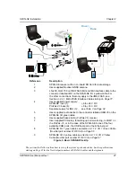
Figure 6: SPAN-SW Power Button
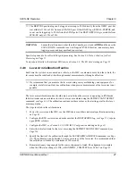
6.
Apply power to the IMU and to the receiver.
It is recommended that a back-up battery is
placed between the receiver and its voltage supply to act as a power buffer if installed in a vehi-
cle. When a vehicle engine is started, power can dip to 9.6 VDC or cut-out to ancillary equipment
causing the receiver and IMU to lose lock and calibration settings.
IMU
Power Requirement
LN-200
+12 to +28 V DC
iIMU-FSAS
+10 to +34 V DC
HG1700
+12 to +28 V DC
Seconds Button is Held
Button Action
3-10 seconds
SPAN-SE is powered off
> 10 seconds
Factory reset (see the FRESET
command on


