Technical Specifications
Appendix A
SPAN-SE User Manual Rev 1
79
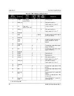
Table 13: FSAS SPAN-SE Y Adapter Cable Pin-Out
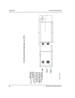
Figure 26: FSAS SPAN-SE Y Adapter Cable
A.2.2.2
iIMU-FSAS Odometer Cabling
The iIMU-FSAS with the –O wheel sensor option provides wheel sensor input from the Distance
Measurement Instrument (DMI) through the DB-9 connector labelled “ODO” on the IMU interface
cable. The IMU data goes through the IMU and then into the SPAN receiver through the serial
communication line.
There are two DMI products that are compatible with the iIMU-FSAS system:
• iMWS-V2 (Magnetic Wheel Sensor) from iMAR
- A magnetic strip and detector are installed inside the wheel. The signal then
goes through a box that translates the magnetic readings into pulses that are
then passed through the cable into the ODO connector on the IMU cable. See
also
below.
• WPT (Wheel Pulse Transducer) from Corrsys Datron
Function
DB-9 Male to FSAS
COM 3 Cable
DB-9 Female to
FSAS I/O Cable
DB-9 Female to
SPAN-SE Cable
(F2
in Figure 26
)
Description
DAS
1
1
Data acquisition and
control signals
DO
2
2
Data output signal /
RS-422(+)
DI
3
3
Data input signal /
RS-422(+)
4
DGND
5
9
5
Digital ground
6
DIN
7
7
Data input signal /
RS-422(-)
DON
8
8
Data output signal /
RS-422(-)
9
F2
F1
M1


