background image

20

SUPERSTAR II User Manual Rev 3

Chapter 3

Installation

In order for the SUPERSTAR II to perform optimally, the following additional equipment is required:

NovAtel GPS antenna

NovAtel coaxial cable

Regulated power supply pro5 VDC

A wiring harness to provide power (connected to J1) as an interface for power, communications 
and signals

Data communication equipment capable of TTL serial communications

See 

Appendix B, FlexPak-SSII Specifications

, starting on 

Page 49

 for a description of the type of enclosure 

equipment required for the receiver to operate.

3.1

Electrostatic Discharge

Electrostatic discharge (ESD) is a leading cause of failure of electronic equipment components and printed 
circuit boards containing ESD-sensitive devices and components. It is imperative that ESD precautions be 
followed when handling or installing the SUPERSTAR II printed circuit board. See also the electrostatic 
discharge notice on 

Page 10 

of this manual.

Leave the SUPERSTAR II in its anti-static packaging when not connected in its normal operating environment. 
When removing the SUPERSTAR II from the ESD-protective plastic, follow accepted standard anti-static 
practices. Failure to do so may cause damage to the SUPERSTAR II.

When you remove the SUPERSTAR II from the original packing box, it is recommended that you save the box 
and ESD protective plastic for future storage or shipment purposes.

REMEMBER!

Always wear a properly grounded anti-static wrist strap when handling the SUPERSTAR II.

Always hold the SUPERSTAR II by its corners or edges, and avoid direct contact with any of the 
components.

Do not let the SUPERSTAR II come in contact with clothing at any time because the grounding 
strap cannot dissipate static charges from fabrics.

Failure to follow accepted ESD handling practices could cause damage to the SUPERSTAR II.

Warranty may be voided if equipment is damaged by ESD. 

3.2

Equipment Interconnection

As mentioned in 

Chapter 1, Introduction, 

starting on 

Page 14

, the receiver can be provided either as an OEM 

board, or within a FlexPak-SSII enclosure. The interconnection of the OEM board format is guided by its 
physical and electrical specifications as detailed in 

Section 3.4, Connectors and Connector Pins Assignment 

starting on 

Page 22

. A complete description of the FlexPak-SSII is provided in 

Appendix B, FlexPak-SSII 

Specifications

, starting on 

Page 49

.

3.2.1

Serial Connection

The receiver includes two serial communication ports. COM1 and COM2 are detailed in 

Section 3.4.2, Serial 

Data Interface 

starting on 

Page 23

. Serial communication with the receiver must be performed on COM1. The 

maximum data transfer rate is 19200 bps. The other serial port, COM2, is used for a differential link, and its 
minimal data transfer rate is 9600 bps. Communication with COM1 and COM2 is through two Deutsch 
connectors on the FlexPak-SSII. 

Please refer to the

 L1 GPS Firmware Reference Manual

 for a discussion on the I/O protocol. 

Summary of Contents for SUPERSTAR II

Page 1: ...OM 20000077 Rev3 SUPERSTAR II User Manual...

Page 2: ...except as specifically allowed in the license or non disclosure agreement No part of this manual may be reproduced or transmitted in any form or by any means electronic or mechanical including photoco...

Page 3: ...nection 20 3 2 1 Serial Connection 20 3 2 2 Power Connection 21 3 3 Installation Considerations 21 3 3 1 Antenna Location 21 3 3 2 Base Station Location 21 3 3 3 Data Link 22 3 3 4 Base Station and Ro...

Page 4: ...tions Fixed 36 5 1 3 RTCM9 Partial Satellite Set Differential Corrections 36 5 2 NMEA Format Data Messages 37 6 Positioning Modes of Operation 38 6 1 Single Point or Autonomous 38 6 1 1 GPS System Err...

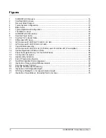
Page 5: ...aces and Power Connector Pin Assignment 47 8 I O Signals Voltage Limits 48 9 FlexPak Status Indicators 50 10 FlexPak COM Ports Pin Out Descriptions 50 11 Coaxial Cable Specifications 56 12 Antenna Gai...

Page 6: ...6 dB 60 14 Coaxial Cable Assembly 60 15 GPS Antenna 201 990147 432 1575 MHz and 201 990144 807 Pre Amplifier 61 16 Update Registration Window in DOS 64 17 Paste the Registration Key into the DOS Windo...

Page 7: ...legal actions concerning this license of the software under this Agreement taken against any third party by NovAtel to protect its rights in the software NovAtel shall bear all reasonable costs and ex...

Page 8: ...or software UPDATES and UPGRADES and regular customer support contact the NovAtel GPS Hotline at 1 800 NOVATEL U S or Canada only or 403 295 4900 or fax 403 295 4901 e mail to support novatel ca visit...

Page 9: ...ng data requests to a file on your PC for 30 minutes Receiver Status ID 49 one shot Ephemeris Data ID 22 continuous Measurement Block ID 23 1 Hz HW SW Identification ID 45 one shot 3 Send the file con...

Page 10: ...ve packing 7 When packing these cards for storage or transportation keep them in the bag Fold over and seal the mouth of the bag to keep out any static generating packing material for example foamed p...

Page 11: ...ent this product may cause radio interference in which case the user may be required to take adequate measures EMC Common Regulatory Testing EN55022 Radiated and Conducted Emissions CISPR 22 Class B E...

Page 12: ...R THAN A NORMAL AND CUSTOMARY MANNER ENVIRONMENTAL CONDITIONS NOT CONFORMING TO NOVATEL S SPECIFICATIONS OR FAILURE TO FOLLOW PRESCRIBED INSTALLATION OPERATING AND MAINTENANCE PROCEDURES II DEFECTS ER...

Page 13: ...nal appendices with reference materials for you Related Publications The related publications are listed in Table 1 Table 1 Related Publications PUBLICATION NAME PUBLICATION NAME 1 ICD GPS 200 Rev B N...

Page 14: ...e Satellite Based Augmentation System SBAS capability for example WAAS and EGNOS When a sufficient number of satellites are tracked with valid measurements the SUPERSTAR II produces a 3 D position and...

Page 15: ...rier phase measurements Message ID 23 Measurement Block Data only works with these models Precise timing 5 Hz PVT output RTCM DGPS Base 1 2 FlexPak SSII The FlexPak SSII see Figure 2 is a hardware int...

Page 16: ...ased a SUPERSTAR II Development Kit the following is also provided with your FlexPak SSII 1 Deutsch to DB 9 serial cable 1 Deutsch to automobile power connector cable 1 AC DC adaptor 1 12 dB active GP...

Page 17: ...chanical packaging of the receiver is designed to allow for mounting within various different configurations of OEM units 2 2 1 Radio Frequency RF Section The receiver obtains a partially filtered and...

Page 18: ...he purpose of the GPS antenna is to convert the electromagnetic waves transmitted by the GPS satellites into RF signals An active or passive GPS antenna may be used in the operation of the receiver No...

Page 19: ...e 13 The SUPERSTAR II is an OEM product designed for flexibility of integration and configuration You are free to select an appropriate data and signal interface power supply system and mounting struc...

Page 20: ...storage or shipment purposes REMEMBER Always wear a properly grounded anti static wrist strap when handling the SUPERSTAR II Always hold the SUPERSTAR II by its corners or edges and avoid direct cont...

Page 21: ...n window or door jambs By default the SUPERSTAR II uses satellites above 4 5 degrees elevation The mask angle can be set to use a different cut off as low as zero degrees all in view using Message ID...

Page 22: ...m number of connections on J1 required for the system to operate is shown in Table 2 Table 2 Minimum J1 Connections If DGPS corrections are required for the application the SUPERSTAR II can receive th...

Page 23: ...upport communication using the binary protocol Through specific binary messages the ports are re configurable to communicate with NovAtel s PC based user interface StarView software for extensive moni...

Page 24: ...rrent on J2 is 40 mA 3 4 3 2 RF Input The receiver will receive the GPS signal from the antenna amplifier on the J2 RF input connector The RF input port impedance is 50 Ohms nominal 3 4 4 Memory Back...

Page 25: ...ivalent Name Use Direction GPIO2 IO1 Navigator IN OUT GPIO3 IO2 SP IN OUT GPIO5 IP1 GPS Data IN OUT GPIO6 IP2 NVM Control IN OUT GPIO7 IP3 Protocol Select IN OUT Disc_IP3 Protocol Select Disc_IP2 NVM...

Page 26: ...e default data transfer rate is 9600 bps unless your receiver model has Carrier Phase Output CP capability in which case it may be 19200 A list of models is in Appendix A of the L1 GPS Firmware Refere...

Page 27: ...ion 3 3 1 on Page 21 4 Connect the GPS antenna to the receiver using an antenna RF cable using the information given in Section 3 4 3 1 Preamplifier Power Pass Through Antenna Supply and Section 3 4 3...

Page 28: ...ring the initial operation and testing for greater ease and versatility Figure 6 Typical Operational Configuration Reference Description 1 L1 GPS card 2 OEM housing 3 Command source or base station 4...

Page 29: ...re Reference Manual and in our Price List available from the Sales side menu of our website at www novatel com The data transfer rate you choose will determine how fast information is transmitted Take...

Page 30: ...w program The receiver s software resides in read only memory As such the unit self boots when turned on and undergoes a complete self test see Section 4 5 2 Operational States starting on Page 31 If...

Page 31: ...ible multipath Typical mask angle values range from 5 10 depending on the receiver s location This value is programmable using command Message ID 81 Set Mask Angle 4 4 2 GPS Antenna Position For the b...

Page 32: ...ion solution Acquisition mode is entered from Initialization or Dead Reckoning mode and exits to Navigation or Fault mode To acquire signals from the GPS satellites the receiver uses Almanac data whic...

Page 33: ...er mode requested or a reset will cause the unit to leave this navigation mode In this mode the unit will have the ability to transmit the DGPS messages which are requested and allowed once its positi...

Page 34: ...e list of the supported datum and details on Message ID 88 Select Define Datum to Use are provided in the L1 GPS Firmware Reference Manual The receiver can also support two user defined datums You mus...

Page 35: ...message Message length is variable and a message can be transmitted up to once every 100 ms A RTCM message always starts as the first byte of a message and always ends as the last byte of a message Th...

Page 36: ...nge corrections based on the old ephemeris Once the rover receiver has collected its own updated ephemeris it will no longer utilize the Type 2 messages The GPS Card will accept and decode RTCM Standa...

Page 37: ...decimal fraction are optional if full resolution is not required Time hhmmss ss Fixed Variable length field hours minutes seconds decimal 2 fixed digits of hours 2 fixed digits of minutes 2 fixed digi...

Page 38: ...as the GPS receiver design and engineering quality There are numerous factors which influence the single point position accuracies of any GPS C A code receiving system As the following list will show...

Page 39: ...any of these satellites and more satellites will be available in the future The primary functions of SBAS include data collection determining ionospheric corrections determining satellite orbits deter...

Page 40: ...k SV enables the use of particular SBAS corrections in the position filter Two SBAS specific messages Message ID 67 SBAS Data Message ID 68 SBAS Status are also available In order to use these message...

Page 41: ...he Valid Messages count is not incrementing it means that either the receiver is not tracking any SBAS satellites or it is unable to demodulate the SBAS bit stream Refer to the L1 GPS Firmware Referen...

Page 42: ...u are experiencing problems with low SNR levels Verify antenna connector look for broken or poor connections on the RF signal shield contacts If using an active antenna verify antenna is receiving cor...

Page 43: ...II Substitute another host hardware Substitute another RF source i e antenna cable Substitute another interconnect harness Substitute alternate power source or isolate main power source from auxiliary...

Page 44: ...nadian export laws Acceleration 4 G 39 2 m s2 Jerk 2 m s3 Altitude 18 km 60 000 ft limited by US and Canadian export laws GENERAL CHARACTERISTICS 12 PARALLEL ALL IN VIEW TRACKING SBAS Support for exam...

Page 45: ...ensions 46 x 71 x 13 mm Weight 22 g Operating Temperature 30 C to 75 C Storage Temperature 55 C to 90 C Humidity 5 to 95 relative humidity non condensing to 60 C SUPERSTAR II DEVELOPMENT KIT Input Vol...

Page 46: ...46 SUPERSTAR II User Manual Rev 3 Appendix A Technical Specifications A 2 1 Mechanical Drawing Figure 8 shows the SUPERSTAR II OEM board outline Figure 8 SUPERSTAR II Dimensions...

Page 47: ...rogrammable discrete I O pin expansion pin for special applications 5 MASTER_RESET Reset input pin active low 6 DISC_IP_1 Reprogramming control input pin active high 7 DISC_IP_2 Protocol select pin se...

Page 48: ...150 ns minimum will invoke a master reset to the receiver 2 Conditions 5 V 0 25 V for all limits SIGNAL NAME TYPE Input low max V Inputhigh min V Outputlow max V Output high min V MASTER_RESET 1 I 0 5...

Page 49: ...t Voltage 6 to 18 VDC Power Consumption 0 7 W typical COM1 13 pin waterproof Deutsch connector Deutsch P N 59065 11 35PF COM2 13 pin waterproof Deutsch connector Deutsch P N 59065 11 35PF PHYSICAL Siz...

Page 50: ...COM1 Green Data is being transmitted from COM1 Red Data is being received on COM1 COM2 Green Data is being transmitted from COM2 Red Data is being received on COM2 ANT Green Valid position computed PW...

Page 51: ...e operating from an automobile The figure below shows the cable and a wiring diagram of the automobile adapter The output of the power adapter uses a 3 pin Deutsch socket Deutsch part number 58064 08...

Page 52: ...he FlexPak and another serial communications device such as a PC At the FlexPak end the cable is equipped with a 13 pin Deutsch connector Deutsch part number 59064 11 35SF which plugs directly into a...

Page 53: ...s your receiver model has Carrier Phase Output CP capability in which case it may be 19200 Your receiver must be a BASE model to act as a base station A list of models is in Appendix A of the L1 GPS F...

Page 54: ...position to agree with latitude longitude and height of the phase center of the base station GPS receiver antenna and the antenna offset position from the base The rover station must be tracking the...

Page 55: ...ble when the CD is inserted select Run from the Start menu and press the Browse button to locate Setup exe on the CD drive 4 Click on the OK button to install the StarView software and follow the step...

Page 56: ...e loss The loss increases with the length of the cable and decreases with extra isolation If the highest accuracy possible is not required receivers can accept a total cable loss of 3 dB Depending on...

Page 57: ...eceiver and the antenna is very short less than one meter a passive antenna could then be considered Table 14 lists the specifications for recommended passive antennas Complete drawings are at the end...

Page 58: ...y of the L1 GPS receivers Table 15 Recommended Active Antennas Prices and availability can be found in the latest Price List on our website at http www novatel com C 4 Passive Antenna For DGPS applica...

Page 59: ...is reason in many cost sensitive applications it may be necessary to select a passive antenna in conjunction with a low loss coaxial cable Figure 12 GPS Antenna 201 990146 716 MCX 12 dB Frequency 1575...

Page 60: ...60 SUPERSTAR II User Manual Rev 3 Appendix C Antenna Specifications Figure 13 GPS Antenna 201 990147 606 26 dB Figure 14 Coaxial Cable Assembly...

Page 61: ...Antenna Specifications Appendix C SUPERSTAR II User Manual Rev 3 61 Figure 15 GPS Antenna 201 990147 432 1575 MHz and 201 990144 807 Pre Amplifier...

Page 62: ...URVEY OF CANADA Natural Resources Canada Geodetic Survey Division Geomatics Canada 615 Booth Street Room 440 Ottawa Ontario Canada K1A 0E9 Phone 613 995 4410 Fax 613 995 3215 E Mail information geod n...

Page 63: ...valid navigation output is typically less than 3 minutes E 2 Re Acquisition Re acquisition is the resumption of tracking and measurement processing There is no disruption of navigation data output whe...

Page 64: ...utility executable file update exe for this example into the newly created folder 3 Select Run from the Start menu and press the Browse button to locate update exe in the Update folder Select update e...

Page 65: ...or example Enter to exit Figure 18 Configuration Accepted F 5 Starting Software and Options Update Once activated the Update utility works until the date or session counter expires Simply follow the i...

Page 66: ...Updating Receiver Firmware F 5 1 Programming Success The Update utility confirms programming success at the end of the programming session see Figure 20 below At this point remove power from your GPS...

Page 67: ...ent All these parts operate together to provide accurate three dimensional positioning timing and velocity data to users worldwide G 1 1 The Space Segment The space segment is composed of the NAVSTAR...

Page 68: ...tracks and receives the satellite signals The user equipment must be capable of simultaneously processing the signals from a minimum of four satellites to obtain accurate position velocity and timing...

Page 69: ...el heights Once this conversion is complete users can relate their GPS derived heights to more usable mean sea level heights G 3 GPS Positioning GPS positioning can be categorized as follows 1 single...

Page 70: ...eivers and hence cancel out in relative measurements Since the position of the base station can be determined to a high degree of accuracy using conventional surveying techniques any differences betwe...

Page 71: ...entire data collection session is complete G 4 Multipath Multipath signal reception is one of the most plaguing problems that detracts from the accuracy potential of GPS pseudorange differential posi...

Page 72: ...fracted and reflected signals generally sustain some degree of signal amplitude attenuation It is generally understood that in multipath conditions both the direct and reflected signals are present at...

Page 73: ...udorange errors become significant due to dominant multipath biases and may exceed 150 meters For single point pseudorange positioning these occasional levels of error may be tolerable as the accuracy...

Page 74: ...rties at low elevation angles near their radiation pattern horizon Quadrifilar helix antennas and other similar vertically high profile antennas tend to have high radiation gain patterns at the horizo...

Page 75: ...a hard boundary condition i e allowing electromagnetic waves to propagate along the ground plane and diffract strongly from its edge The soft boundary condition on the other hand will prevent the wav...

Page 76: ...orbital parameters and synchronize their clocks Differential GPS DGPS a technique to improve GPS accuracy that uses pseudorange errors measured at a known location to improve the measurements made by...

Page 77: ...and time data When fully operational GPS will provide this data free of direct user charge worldwide continuously and under all weather conditions The GPS constellation will consist of 24 orbiting sa...

Page 78: ...GPS civilian users on a continuous worldwide basis typically using C A code SV Space Vehicle ID sometimes used as SVID also used interchangeably with Pseudo Random Noise Number PRN TDOP Time Dilution...

Page 79: ...requirements and the accuracy of the measuring device WGS 84 World Geodetic System 1984 is an ellipsoid designed to fit the shape of the entire Earth as well as possible with a single ellipsoid It is...

Page 80: ...n dB Decibel dBm Decibel Relative to 1 milliWatt DGNSS Differential Global Navigation Satellite System DGPS Differential Global Positioning System DOP Dilution Of Precision ECEF Earth Centered Earth F...

Page 81: ...cond NVM Non Volatile Memory OCXO Oven Controlled Crystal Oscillator OEM Original Equipment Manufacturer PC Personal Computer PCB Printed Circuit Board P Code Precise Code PDOP Position Dilution Of Pr...

Page 82: ...SRAM Static Random Access Memory SV Space Vehicle TCXO Temperature Compensated Crystal Oscillator TDOP Time Dilution Of Precision TTFF Time To First Fix UTC Universal Time Coordinated VDOP Vertical D...

Page 83: ...enna 56 coaxial 17 60 interface 54 RF 24 serial 29 warranty 12 carrier phase multipath errors 73 cautions 29 CD 55 clock bias 70 data 68 drift 36 external 36 coaxial 17 20 56 60 communication 20 29 42...

Page 84: ...9 22 24 47 ionosphere 38 J jerk 44 K kinematic versus static 71 kit development 45 53 L latency 36 latitude 67 L band 67 license software 7 LNA see low noise amplifier longitude 67 low noise amplifier...

Page 85: ...7 multipath 72 74 orbit arrangement 67 records number of 29 tracking 14 transmit 18 SBAS 39 40 scope 13 segment control 67 68 space 67 user 67 68 self test 30 32 33 63 serial cable 29 communication 44...

Page 86: ...86 SUPERSTAR II User Manual Rev 3 Index W warm start 24 warnings 11 18 warranty 12 18 20 website 62 weight 45...

Page 87: ...OM 20000077 Rev 3 2004 03 11...

Reviews: